Short-circuit prevention in an RF spark plug

a short-circuit prevention and spark plug technology, applied in spark plug manufacture, spark plugs, electrical equipment, etc., can solve the problems of reducing the efficiency of the spark plug, the method of obtaining discharges is actually undesirable, and the ignition in the presence of lean gas/fuel mixtures is difficult to control, so as to reduce the space requirement of the device and the effect of simple assembly

Inactive Publication Date: 2013-09-12
RENAULT SA
View PDF3 Cites 15 Cited by
  • Summary
  • Abstract
  • Description
  • Claims
  • Application Information

AI Technical Summary

Benefits of technology

[0036]The conical bore in the upper part of the insulating component is adapted to accommodate th

Problems solved by technology

Ignition in the presence of a lean gas/fuel mixture is difficult to control.
This method of obtaining discharges is actually undesirable because it reduces the efficiency of the spark plug.
Variant embodiments can be used to reduce electric field enhancements notably by removing the right angles on said shoulder causing electric arcing between the insulating component and the shell, which is detrimental to the efficiency of the spark plug.
This architecture leads to manufacturing and assembly constraints, making it necessary, for example, to assemble the insulating material component in the shell in the opposite direction due to the shoulder at the end of the insulating component.
However, problems arise at the edge of the metalization area on the isolator facing the shell.
As e

Method used


Image

  • Short-circuit prevention in an RF spark plug
  • Short-circuit prevention in an RF spark plug
  • Short-circuit prevention in an RF spark plug

Examples


Embodiment Construction

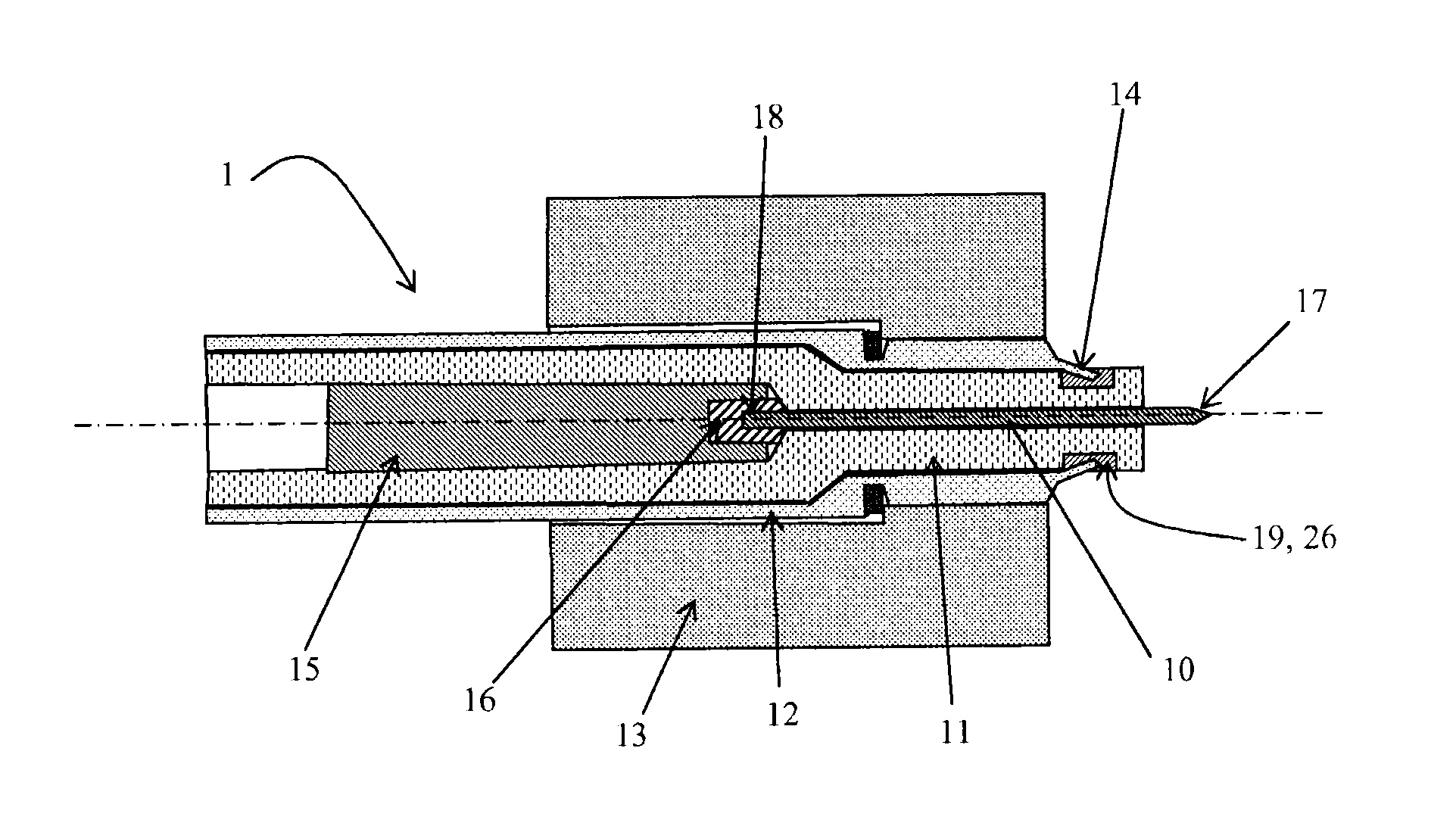
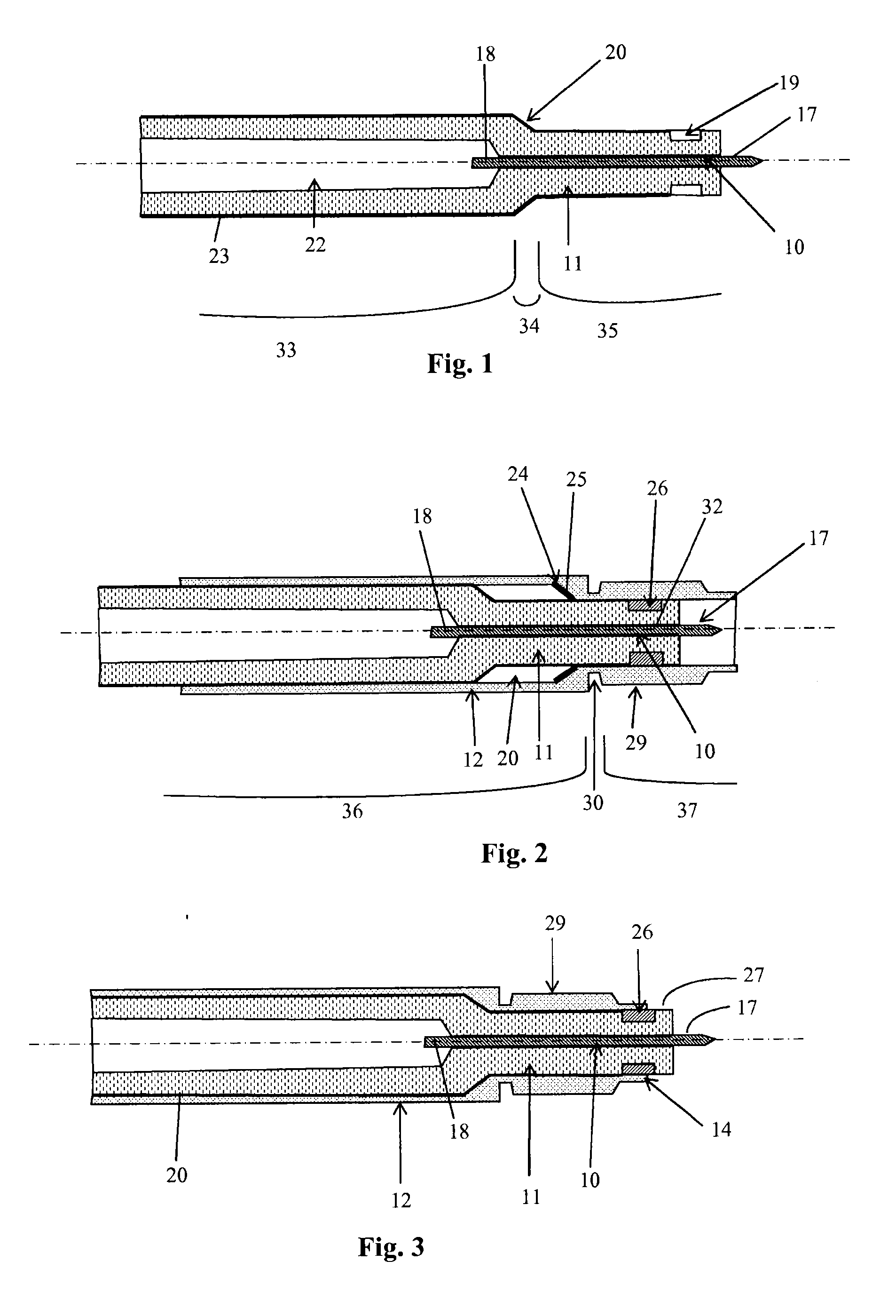
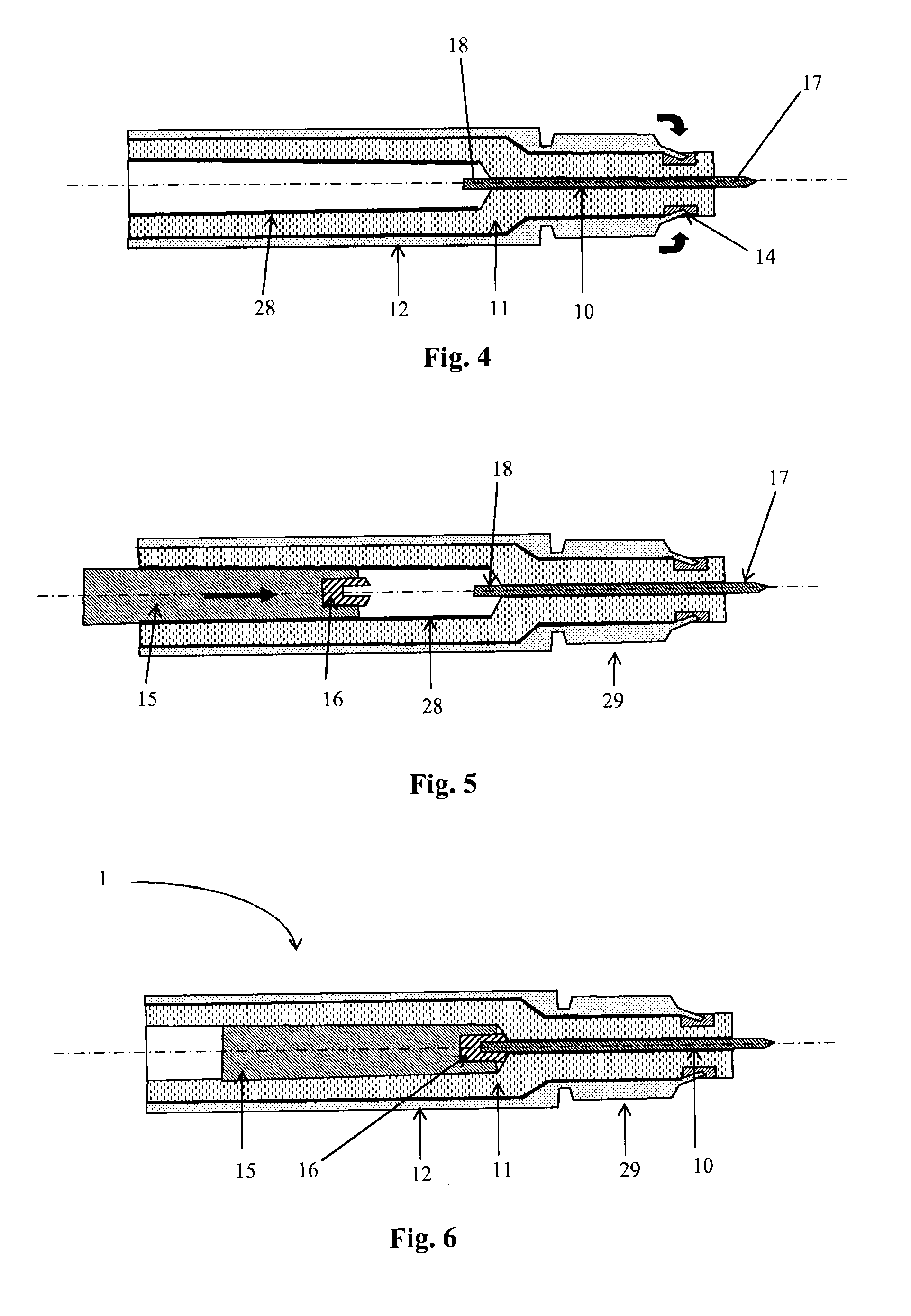
[0048]According to the invention, with reference to FIG. 1, an electrode 10 of substantially cylindrical shape made of conducting material, and including an upper end 18 and a lower end 17 intended to be in contact with the gas mixture, is maintained by any means (brazing, bonding, sintering, etc.) ensuring a tight contact, in a bore of an insulating component 11 so that the lower end 17 of the electrode extends beyond the component 11.

[0049]The insulating component 11 is of a single-body type and comprises two end segments 33 and 35 of a substantially tubular shape and different outer diameters and a third segment 34 forming the connection between the two segments 33 and 35. The first segment 35 surrounds the central electrode 10 over a portion of its outer surface, and has an annular groove 19 near the lower end 17 of the central electrode 10. The second segment 33 of a substantially larger outer diameter comprises a slightly conical inner bore 22. The average diameter of this bor...


PUM


Abstract

A spark plug including: a central electrode including an upper end and a lower end; an insulating part including an upper portion and a lower portion and surrounds the central electrode so that the lower end of the central electrode extends beyond the lower portion of the insulating part; and a cap including an upper portion and a lower portion that has an end section and that surrounds the insulating part so that the lower portion of the insulating part extends beyond the lower portion of the cap. The insulating part includes an annular groove, on the external periphery thereof, on the lower end of the cap, and the lower end section of the cap is placed in the groove.

Description

TECHNICAL FIELD TO WHICH THE INVENTION IS RELATED[0001]The invention relates to radiofrequency plasma spark plugs. The invention relates more particularly to radiofrequency plasma spark plugs intended to be fitted in the combustion chambers of internal combustion engines and which comprise a central electrode of cylindrical shape consisting of a conductive material, which comprises an upper end and a lower end intended to be arranged in the combustion chamber, a component substantially tubular in shape, made of an electrically insulating material, which includes an upper part and a lower part, and which surrounds the central electrode over a portion of its length so that the lower end of the central electrode extends beyond the lower part of the insulating material component, a steel shell substantially tubular in shape, which includes an upper part and a lower part, and which surrounds the insulating material component over a portion of its length so that the lower part of the insu...

Claims


Application Information

Patent Timeline
IPC IPC(8): H01T13/34
CPCH01T13/50H01T13/34H01T21/02H01T13/52
Inventor MAKAROV, MAXIMEPARIENTE, MARC
Owner RENAULT SA
Why Eureka
Try Eureka