Power supply device and image forming apparatus

a technology of power supply device and image forming apparatus, which is applied in the direction of electric variable regulation, process and machine control, instruments, etc., can solve the problems of low switching frequency, loss of switching power supply in light load operation, and increase in transformer size, so as to reduce vibration noise and reduce power consumption

Active Publication Date: 2013-09-12
CANON KK
View PDF3 Cites 20 Cited by
  • Summary
  • Abstract
  • Description
  • Claims
  • Application Information

AI Technical Summary

Benefits of technology

[0011]A purpose of the present invention is to reduce vibration noise generated from a transformer in a light load operation and reduce power consumption.

Problems solved by technology

Most of the losses of the switching power supply in the light load operation are caused by the switching operation.
The long inactive period of the switching operation, however, leads to a low switching frequency.
However, the above-mentioned methods of reducing the vibration noise of the transformer have the following problems.
According to the method of using a core material having a large cross-sectional area for the transformer, the transformer is increased in size, and hence it is difficult to downsize the power supply device.
However, the number of switchings per unit time increases, and the switching loss increases, resulting in control unfavorable to power saving.
Further, the method of changing the driving current waveform of the transformer to be gradually larger or gradually smaller is difficult to be applied to the case of the light load operation where energy to be supplied to a load on the secondary side of the transformer is small.
In other words, this method is difficult to be applied because the inactive period of the switching operation is provided in the light load operation and it is therefore difficult for the soft-start circuit to change the current waveform to be gradually larger or gradually smaller.
In particular, when the driving frequency of the switching element matches with the resonant frequency of the transformer, the sound pressure level becomes very high.
Therefore, if the switching element is driven at the resonant frequency of the transformer, a conspicuously recognizable harsh noise is generated from the transformer.
In the above-mentioned conventional methods, the control of reducing the vibration noise is not performed in accordance with the characteristics of the transformer, and hence there has been a problem in that the vibration noise cannot be suppressed effectively in the switching operation in the light load operation.

Method used


Image

  • Power supply device and image forming apparatus
  • Power supply device and image forming apparatus
  • Power supply device and image forming apparatus

Examples


first embodiment

[0064]In this embodiment, description is given below of a DC power supply device in which a turn-ON time of the FET 107 is shortened at a specific switching frequency to reduce energy to be accumulated in the transformer, to thereby reduce vibration noise of the transformer.

[0065][Outline of Correction Circuit]

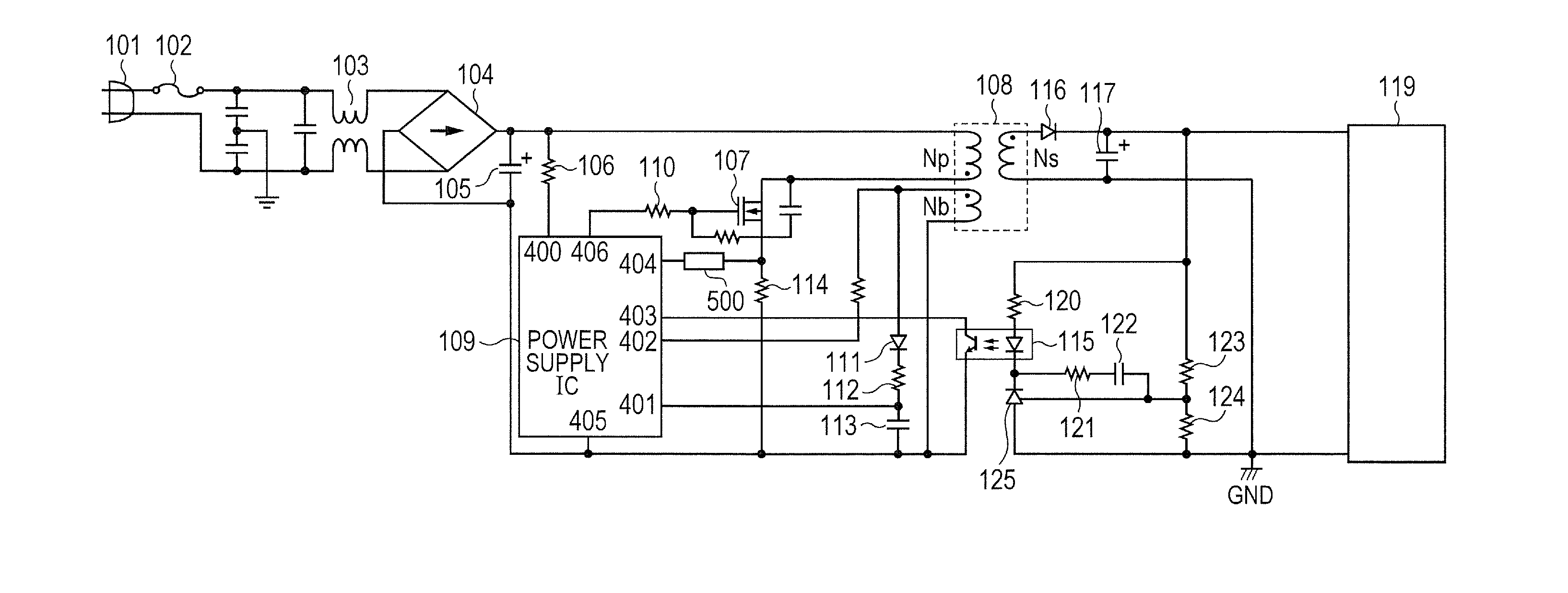
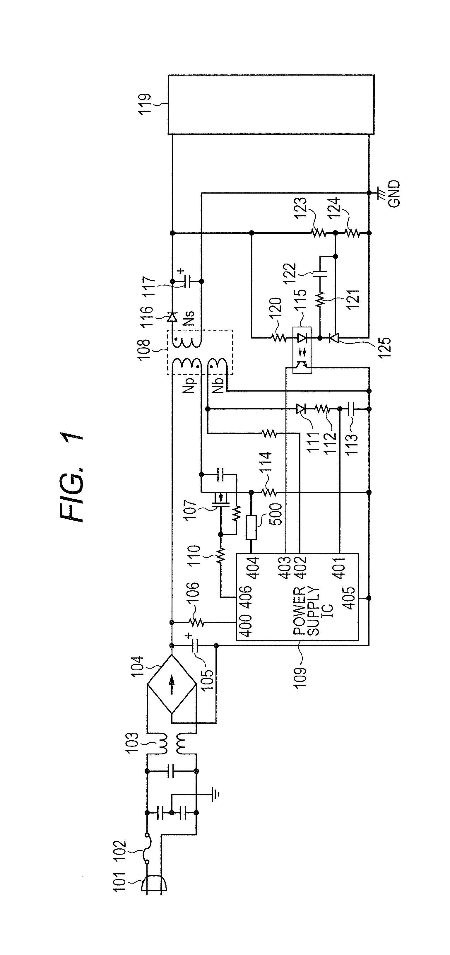
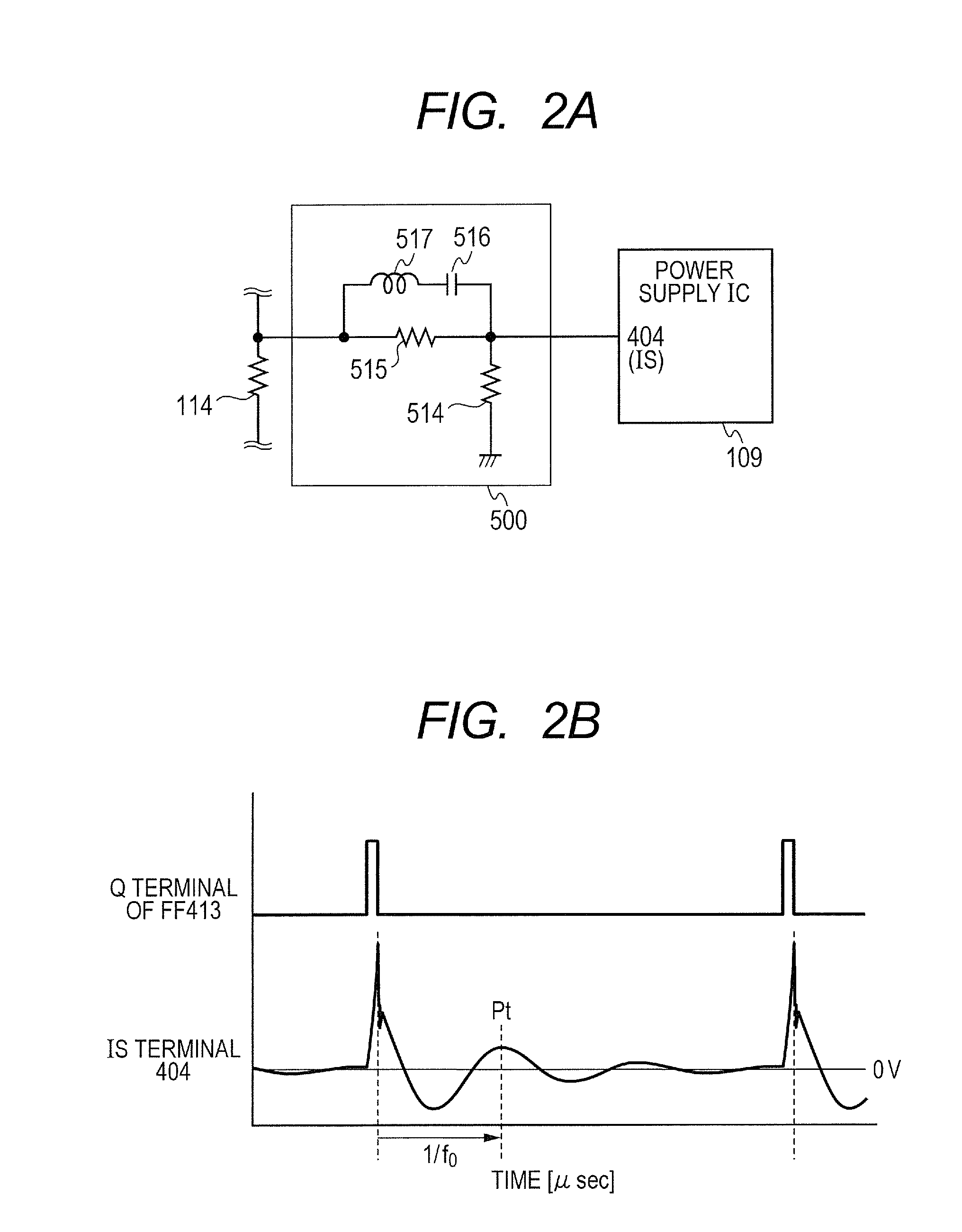
[0066]FIG. 1 illustrates a circuit configuration of the DC power supply device in this embodiment. The circuit configuration of FIG. 1 is different from the conventional circuit configuration of FIG. 10A described above in that an IS terminal voltage correction circuit 500 is provided in front of the IS terminal 404 of the power supply IC 109 for detecting a drain current Id of the FET 107. The IS terminal voltage correction circuit 500 (hereinafter referred to as “correction circuit 500”) is a circuit for changing the voltage waveform input to the IS terminal 404 in accordance with the switching frequency when the FET 107 is in the OFF state. The circuit configuration illustr...

second embodiment

[0079]In this embodiment, description is given below of a DC power supply device in which the timing of turning ON the FET (switching cycle) is delayed so that the FET does not become conductive at a specific frequency, that is, the resonant frequency of the transformer, to thereby reduce vibration noise of the transformer.

[0080][Outline of Correction Circuit]

[0081]FIG. 4A illustrates a circuit configuration of the DC power supply device in this embodiment. The circuit configuration of FIG. 4A is different from the above-mentioned circuit configuration of the conventional DC power supply device of FIG. 10A in the following points. That is, a regulation resistance correction circuit 501 is inserted and connected in parallel to the resistor 123 (first resistor) provided on the secondary side of the transformer 108, and a control unit 800 for controlling the regulation resistance correction circuit 501 and a memory 801 are provided in the load 119. The circuit configurations of the fir...

third embodiment

[0094]In this embodiment, description is given below of a DC power supply device in which the turn-ON time of an FET as a switching element is controlled in accordance with a switching frequency with the use of a control IC formed of a digital circuit instead of the power supply IC for power supply control used in the first and second embodiments.

[0095]FIG. 6 illustrates a circuit configuration of the DC power supply device in this embodiment. FIG. 6 of this embodiment is different from FIG. 10A of the conventional example, FIG. 1 of the first embodiment, and FIG. 4A of the second embodiment in that, while the drive control of the FET 107 in the conventional example and the first and second embodiments is performed by the power supply IC 109, the drive control of the FET 107 in this embodiment is performed by a control IC 503. The circuit configuration except for the control IC 503 (hereinafter referred to as “IC 503”) is the same as in the conventional example, and hence descriptio...


PUM


Abstract

The power supply device includes a transformer, a switching unit for driving a primary side of the transformer, a detection unit for detecting an output corresponding to a current flowing on the primary side, a transmission unit for transmitting an output voltage from a secondary side to the primary side, and a control unit for controlling an operation of the switching unit in accordance with an output from the transmission unit, in which, when a switching frequency for driving the switching unit falls within a predetermined frequency range including a resonant frequency of the transformer, the control unit controls the switching unit so as to shorten a turn-ON time of the switching unit in accordance with an output from the detection unit.

Description

BACKGROUND OF THE INVENTION[0001]1. Field of the Invention[0002]The present invention relates to a self-excited flyback switching power supply device for converting a high direct current voltage obtained by rectifying and smoothing a commercial power supply into a low direct current voltage necessary for a device, and to an image forming apparatus including the power supply device.[0003]2. Description of the Related Art[0004]In recent years, power saving is required in various electronic devices. Following the demands, further power saving is required also for a power supply of the electronic devices. As an example of the power supply of the electronic devices, there is used a switching-mode power supply (hereinafter referred to as “switching power supply”) for outputting a target voltage by driving a switching element such as a field effect transistor (FET) at a predetermined frequency. In some types of the switching power supply, the number of switching operations of the switching...

Claims


Application Information

Patent Timeline
Patent Type & Authority Applications(United States)
IPC IPC(8): G03G15/00H02M3/335
CPCG03G15/80Y02B70/1433H02M3/33523H02M3/33507Y02B70/10H02M1/0025H02M1/0032H02M1/0006H02M1/0009G03G15/00H02M3/28H02M3/335
Inventor SHOJI, RYUHEIAOKI, MASARUHAYASAKI, MINORU
Owner CANON KK
Why Eureka
Try Eureka