
Advanced aerodynamic and structural blade and wing design

a technology of aerodynamics and structural blades, applied in the direction of liquid fuel engines, vessel construction, marine propulsion, etc., can solve the problems of reducing aerodynamic efficiency, none of the approaches that have sufficiently addressed the structural load challenge of the turbine blade growth, etc., to achieve the effect of reducing the overall weight and structural requirements of the tower, reducing the amount of material, and increasing the rigidity of the tower

Inactive Publication Date: 2013-09-12
RGT UNIV OF CALIFORNIA
View PDF3 Cites 5 Cited by
  • Summary
  • Abstract
  • Description
  • Claims
  • Application Information

AI Technical Summary

Benefits of technology

The patent describes a device that improves the wind turbine blade by using a special shape that increases its aerodynamic efficiency and makes it stronger. This shape, called a biplanar airfoil section, has beneficial effects on the blade's inboard section, which is the part closest to the wind turbine. This makes the blade more effective at converting wind into energy.

Problems solved by technology

Since these thick airfoils exhibit relatively poor aerodynamic performance, current wind turbine blade performance and length is limited by the competing needs to reduce airfoil thickness for performance and increase the blade root thickness to accommodate structural and dynamic loads.
However, non-planar and multiplanar designs are still considered by some investigators.
This has been achieved to a certain extent by means of synthetic jets, trailing edge flaps and wedges, stall strips, and vortex generators, though none of these approaches has sufficiently addressed the structural loading challenge for turbine blade growth.
For most of the flow control approaches mentioned above, the increase in lift for the inboard sections is accompanied by increased drag, which decreases the aerodynamic efficiency.
The manufacturing of larger wind turbines has been hindered previously by the structural limitations that arise when equipping turbines with longer blades, and hence higher loads requiring more rigid inboard supporting structures, to the point where the inboard section of larger blades ceases its aerodynamic purpose in exchange for a sound structural support for the rest of the blade.
Current blades have already proven to be most inefficient at the inboard section due to their near circular cross section.
As a result, these stout inboard sections cannot start the rotors and require energy input to start the rotor and are an aerodynamic liability during nominal operation.

Method used


Image

  • Advanced aerodynamic and structural blade and wing design
  • Advanced aerodynamic and structural blade and wing design
  • Advanced aerodynamic and structural blade and wing design

Examples


Embodiment Construction

[0040]The detailed description set forth below in connection with the appended drawings is intended as a description of presently-preferred embodiments of the invention and is not intended to represent the only forms in which the present invention may be constructed or utilized. The description sets forth the functions and the sequence of steps for constructing and operating the invention in connection with the illustrated embodiments. However, it is to be understood that the same or equivalent functions and sequences may be accomplished by different embodiments that are also intended to be encompassed within the spirit and scope of the invention.

[0041]The present disclosure provides an improved wind turbine and airplane wing design while maintaining or improving blade structural characteristics by incorporating a biplane inboard section.

[0042]Results from analysis of this concept are provided below using a biplane composed of SC2-0714 airfoils as the alternative to the thick inboar...


PUM


Abstract

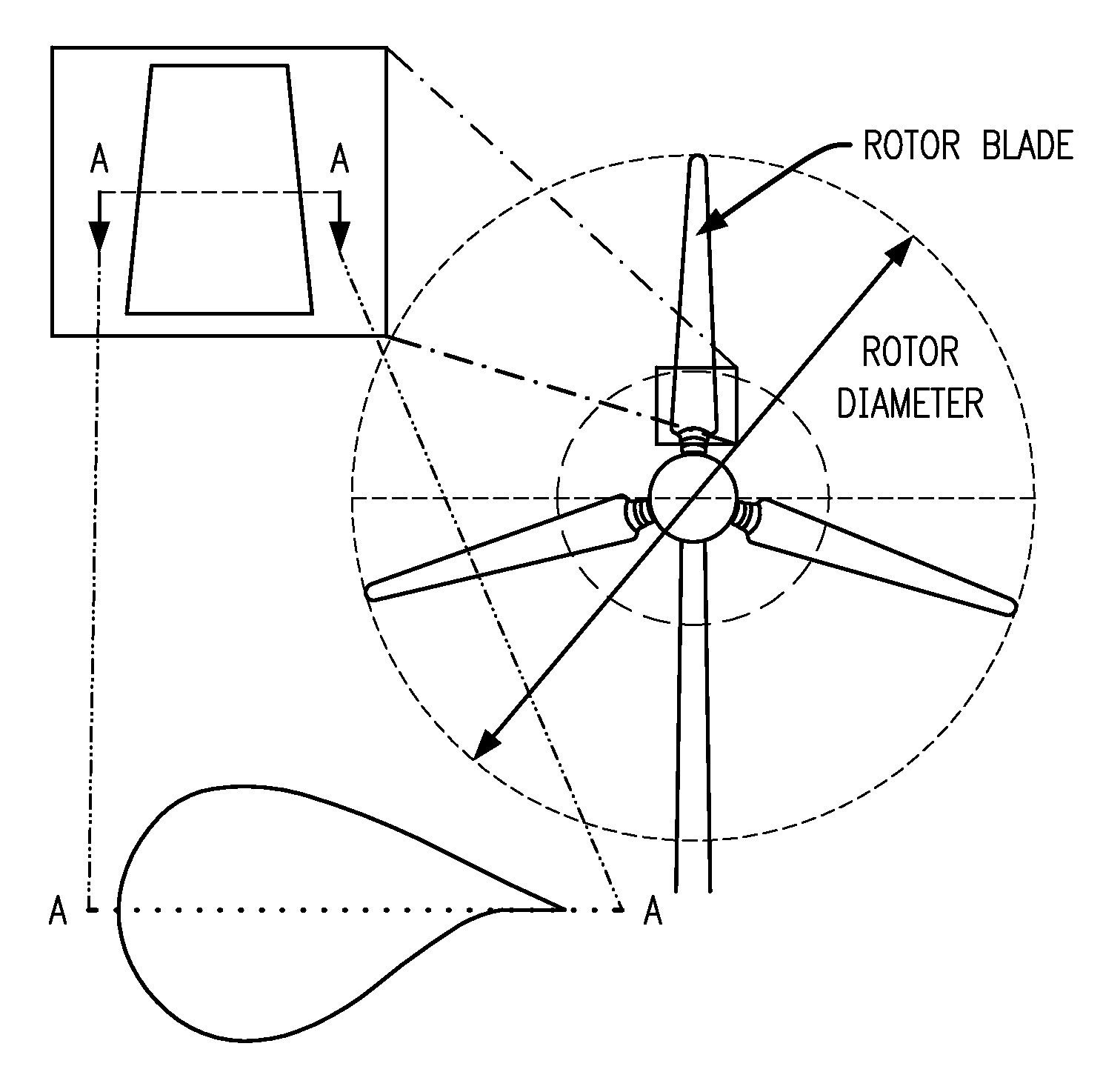
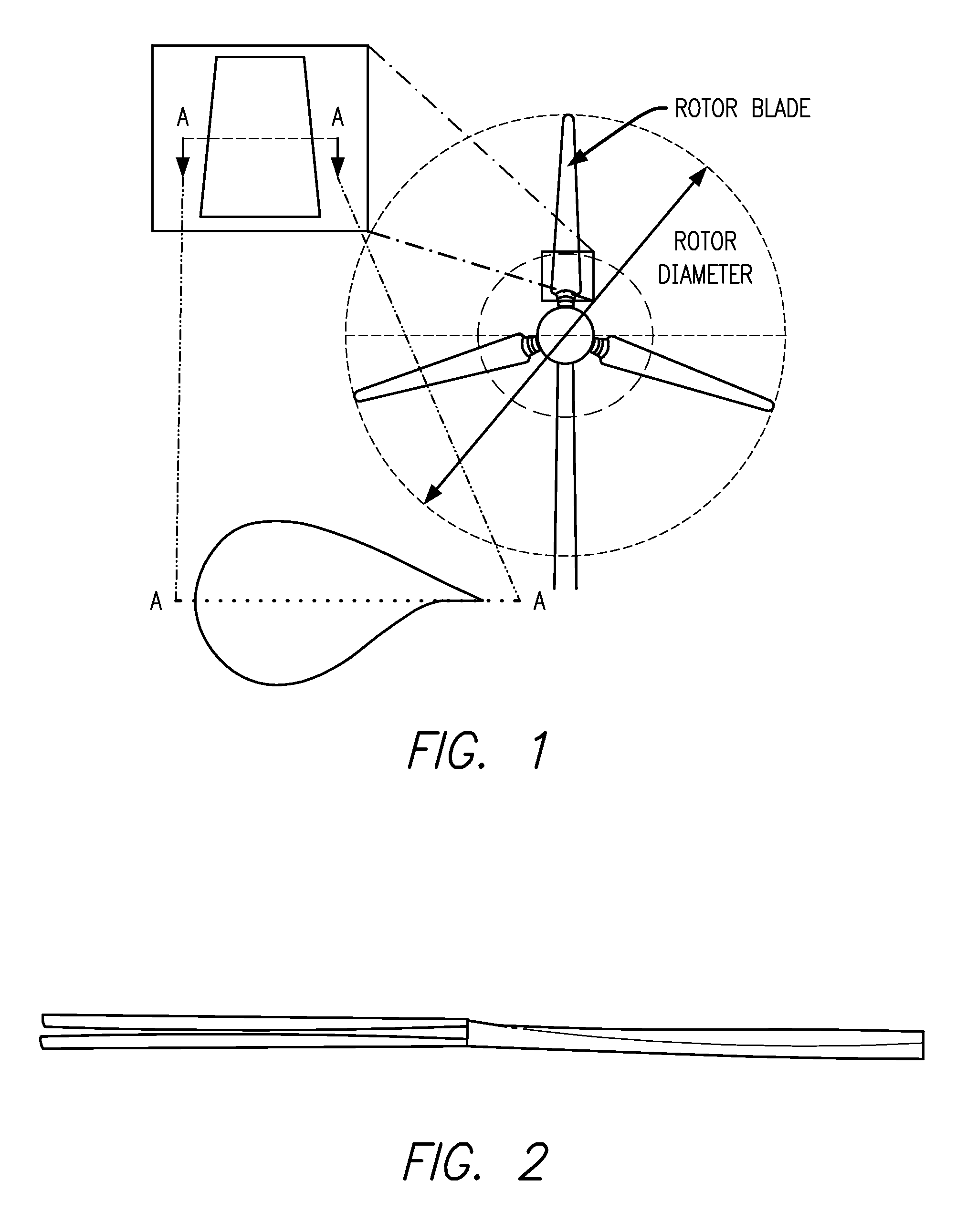
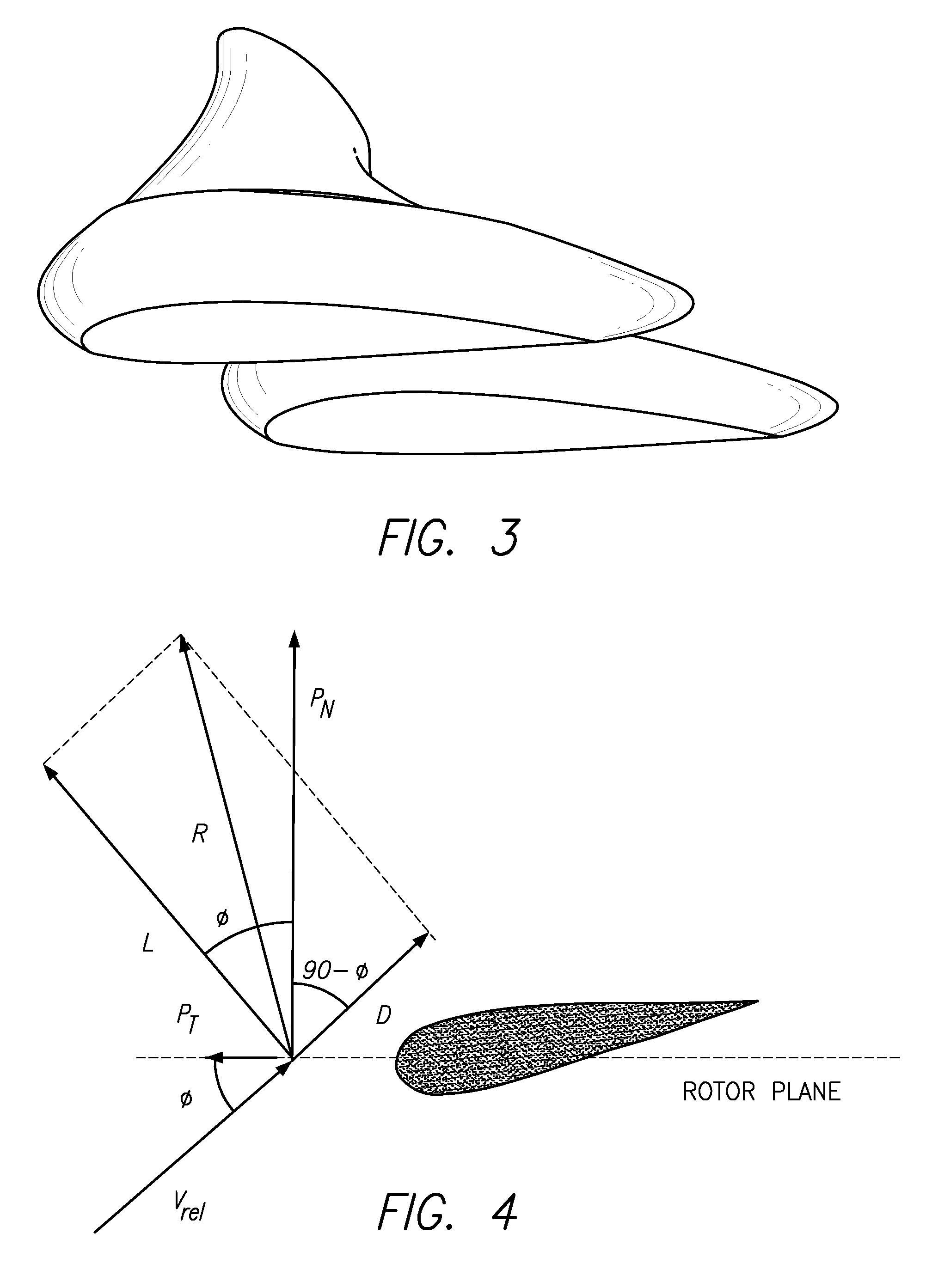
An airfoil having an inboard blade section (106) and an outboard blade section (108). The inboard blade section (106) has a mid-blade end (114), and the inboard blade section (106) includes a biplane wing (116). The multiplane wing (116) has a first blade (118) and a second blade (120). The first blade (118) has a first airfoil cross-section (122), and the second blade (120) has a second airfoil cross-section (132). The first blade (118) is generally parallel to the second blade (120). The outboard blade section (108) has a mid-blade end (148), and the outboard blade section (108) includes a monoplane wing (156) with a third airfoil cross-section (158). The mid-blade end (148) of the outboard blade section (108) is joined to the mid-blade end (114) of the inboard blade section (106).

Description

CROSS-REFERENCES TO RELATED APPLICATIONS[0001]This patent application claims the benefit of U.S. Provisional Patent Application Ser. No. 61 / 308,214 filed Feb. 25, 2010 for Advanced Aerodynamic and Structural Blade and Wing Design. That application is incorporated here by this reference.TECHNICAL FIELD[0002]This invention relates to blade designs for fluid turbine blades, wings, pumps, and propellers.BACKGROUND ART[0003]Wind turbine blades currently use airfoil cross-sections that are very thick near the root (near the rotor hub) to accommodate the large loads on this region of the blade. Since these thick airfoils exhibit relatively poor aerodynamic performance, current wind turbine blade performance and length is limited by the competing needs to reduce airfoil thickness for performance and increase the blade root thickness to accommodate structural and dynamic loads.[0004]Early planes often used two or more wings to increase lifting surface area, but modern single wing designs hav...

Claims


Application Information

Patent Timeline
Patent Type & Authority Applications(United States)
IPC IPC(8): F03D1/06
CPCF03D1/0641F03D1/065F05B2240/301F03D1/0675F05B2250/312Y02E10/721F05B2240/40Y02E10/72
Inventor WIRZ, RICHARD E.
Owner RGT UNIV OF CALIFORNIA
Learn More