Energy Transforming Unit and Energy Transforming System Comprising Such a Unit

a technology of energy transformation and energy transforming unit, which is applied in the direction of dynamo-electric machines, rotary piston engines, engine lubrication, etc., can solve the problems of large and often land-based owc-constructions with very low efficiency, difficult for air turbines to handle large variations in pressure and flow, and avoid internal fluid leakage and/or external fluid suction. , the effect of effective translation

Active Publication Date: 2013-09-12
CORPOWER OCEAN
View PDF10 Cites 6 Cited by
  • Summary
  • Abstract
  • Description
  • Claims
  • Application Information

AI Technical Summary

Benefits of technology

[0027]An important factor for a long life is, among other things, to prevent cavitation. Due to this, the fluid in the energy converter should not be in direct contact with possible volumes of gas in the same. This is prevented by delimiting the reciprocating fluid between two restriction devices, preferably, but not necessarily, of the same size, where for example the secondary restriction device directly or indirectly by a piston conveys the pressures from an external or internal compliance chamber to the opposite restriction device. If the restriction devices are constructed having different sizes, a smaller bypass flow can be created, which for example through an oil filter can be conducted directly to a possible compliance chamber. Further, embodiments with hydraulic conversion modules have been constructed and dimensioned to so that the pressure fall across the conversion modules does not need to be reduced more than approximately 1-4 times in order to obtain nominal effects.
[0064]This embodiment makes it possible to directly produce power using a generator without having to use a conversion module. When the external force acts on a restriction device in the shape of a bellow or an elastic straight or spiral shaped elastomeric cylinder with a hermetically sealed top, it is possible to use the energy in the reciprocating movements without using a piston shaft with a necessary piston shaft seal which is difficult to dimension. Thus, the inside volume of the unit can be hermetically sealed and problems with leakage of internal fluid and / or suction of external fluid can be avoided.

Problems solved by technology

In order to achieve these goals it is not enough to use different types of block diagrams to disclose how a certain energy transformer converts wave movement into for example rotational movements, not without at the same time describe why this certain construction have the requirements for a long lifetime with low supervision and maintenance cost.
The large and often land based OWC-constructions have a very low efficiency.
This is, among other things, due to the difficulty for the air turbines to handle large variations in pressure and flow, which is the result of the reciprocating movement of the air.
The size of the buoys and the migration of the gases through the flexible buoy material may cause long-term problems.
The life of the seemingly very simple and easily comprehensible constructions is in terms of rope- and wire constructions very short, even during the most optimal conditions.
Another troublesome factor regarding these purely mechanical constructions is to find lasting solutions to protect systems when they reach their closing position.
Shock absorbers in the form of steel springs and rubber can be heavy, volume-consuming and create back springing forces that are not always positive.
The problems with these generators are, despite today's magnetic materials, that they in relation to fast rotating generators are bulky, heavy and expensive.
Furthermore, these systems can't as individual sources of power, be provided with simple devices that levels out energy production.
The large pressure differences can create problem of gas migration between the accumulator tanks, thus frequent controls must be performed.

Method used


Image

  • Energy Transforming Unit and Energy Transforming System Comprising Such a Unit
  • Energy Transforming Unit and Energy Transforming System Comprising Such a Unit
  • Energy Transforming Unit and Energy Transforming System Comprising Such a Unit

Examples


Embodiment Construction

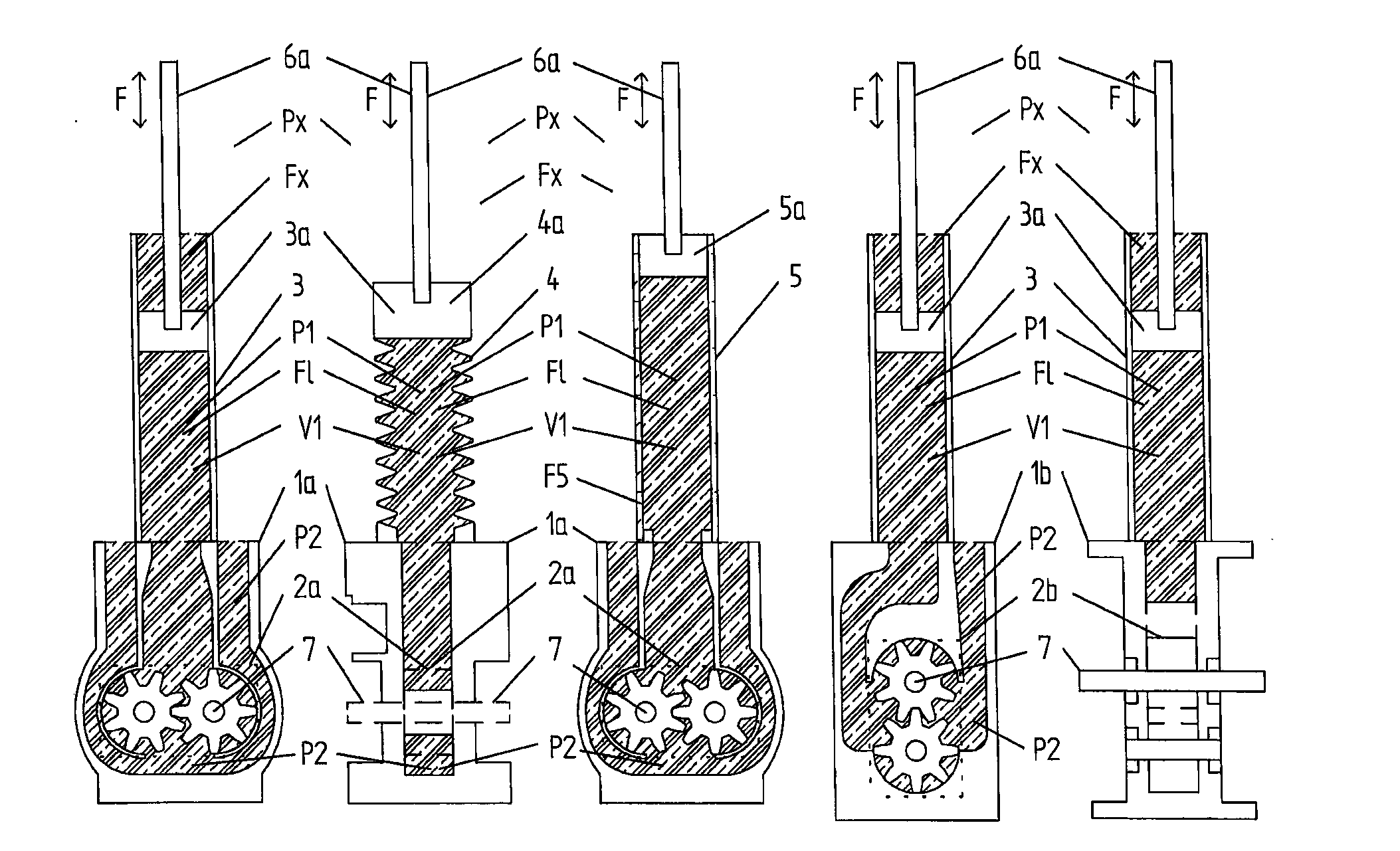
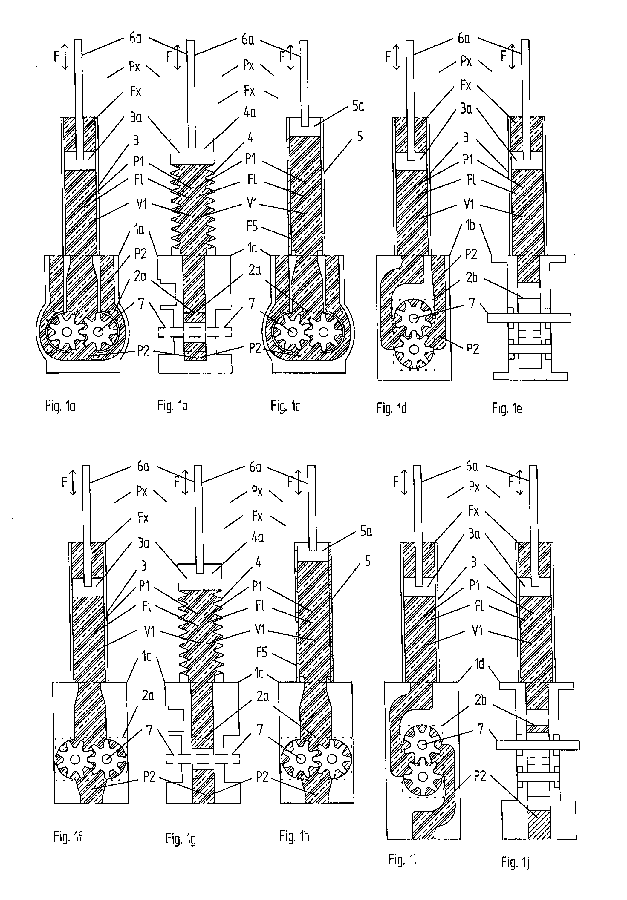
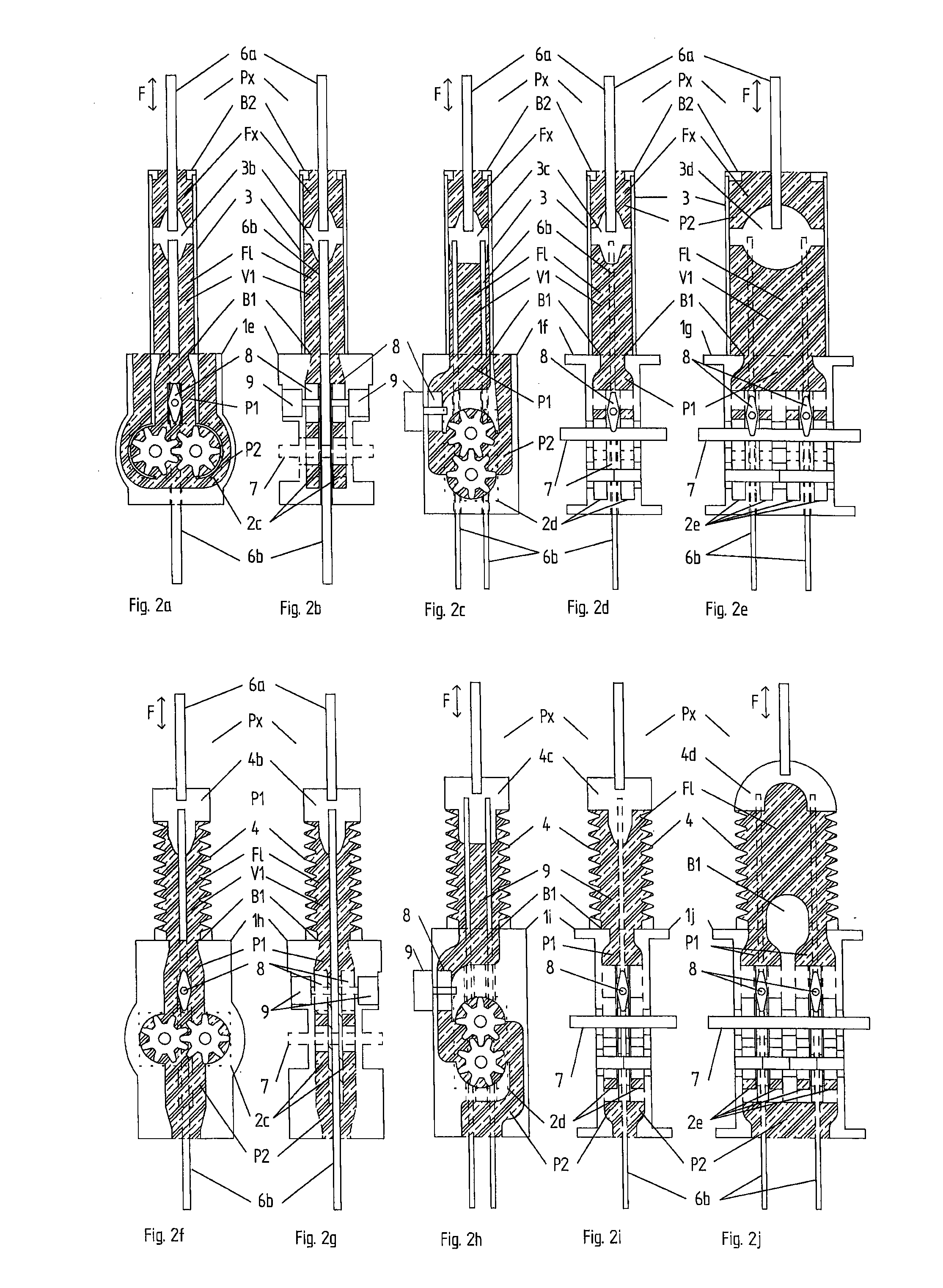
[0096]In the following a detailed description of embodiments of the present invention will be given. It will be appreciated that these figures are for illustration only and are not in any way restricting the scope of the invention. Thus, any references to direction, such as “up” or “down”, are only referring to the directions shown in the figures. Also, any dimensions etc. shown in the figures are for illustration purposes.

[0097]It must be noted that, as used in this specification and the appended claims, the singular forms “a,”“an,” and “the” include plural referents unless the context clearly dictates otherwise.

[0098]Elasticity is to be understood as a materials ability to deform in an elastic way. Elastic deformation is when a material deforms under stress (e.g. external forces), but returns to its original shape when the stress is removed. A more elastic material is to be understood as a material having a lower modulus of elasticity or Young's modulus. The elastic modulus of an ...


PUM


Abstract

The present invention relates to an energy transforming unit adapted to convert reciprocating forces (Fl) into rotating axle movements on at least one force transmitting axle and / or into electrical power. The unit comprises at least one restriction device (3, 4, 5) which is directly connected to the force and which is arranged to forward the incoming reciprocating forces (Fl) into a movement over at least one conversion module (2a-d, 56, 64, 73, 80, 81, 87, Cm). The energy transforming unit is characterized in that the at least one restriction device (3, 4, 5) is delimiting one, by the energy transforming unit enclosed reciprocating volume which entirely or partly passes through the at least one conversion module (2a-d, 56, 64, 73, 80, 81, 87, Cm). The reciprocating volume can comprise a non-compressible fluid arranged to forward the incoming forces into a reciprocating fluid movement over the at least one conversion module (2a-d, 56, 64, 73, 80, 81, 87, Cm) and / or the reciprocating volume can comprise at least one mechanical force transmitting arrangement adapted to the at least one conversion module. The unit further comprises a compact central unit (1a-q) which at least partly encloses the at least one conversion module.

Description

TECHNICAL FIELD[0001]The present invention relates generally to an energy transforming unit adapted to convert reciprocating fluid movements into rotating axle movements. The invention also relates to an energy transforming system, for example a wave power plant, comprising such a unit.BACKGROUND ART[0002]Ocean waves generate both horizontal and vertically rotating oscillating movements, as described in patent application US2007 / 0158950 and patent application U.S. Pat. No. 7,385,301. The oscillating movements can contain tens and sometimes hundreds of kW per running meter wave and has therefore been subjected to several attempts of creating systems that are able to convert this enormous amount of energy into useful and competitive energy transformers converting the energy into for example electric power. In order to achieve these goals it is not enough to use different types of block diagrams to disclose how a certain energy transformer converts wave movement into for example rotati...

Claims


Application Information

Patent Timeline
Patent Type & Authority Applications(United States)
IPC IPC(8): F01C1/14
CPCF03B13/189F05B2260/406F01C1/14Y02E10/38F03B13/187Y02E10/30F03B13/1845F04C2/18H02K35/00
Inventor LUNDBACK, STIG
Owner CORPOWER OCEAN
Why Eureka
Try Eureka