
Turbine nozzle segment and corresponding gas turbine engine

a gas turbine engine and turbine nozzle technology, applied in the direction of machines/engines, stators, mechanical equipment, etc., can solve the problems of only being effective, affecting the efficiency of the barrier coating, so as to reduce the local fluid velocity, avoid losses, and reduce the heat transfer coefficient

Inactive Publication Date: 2013-09-19
SIEMENS AG
View PDF4 Cites 3 Cited by
  • Summary
  • Abstract
  • Description
  • Claims
  • Application Information

AI Technical Summary

Benefits of technology

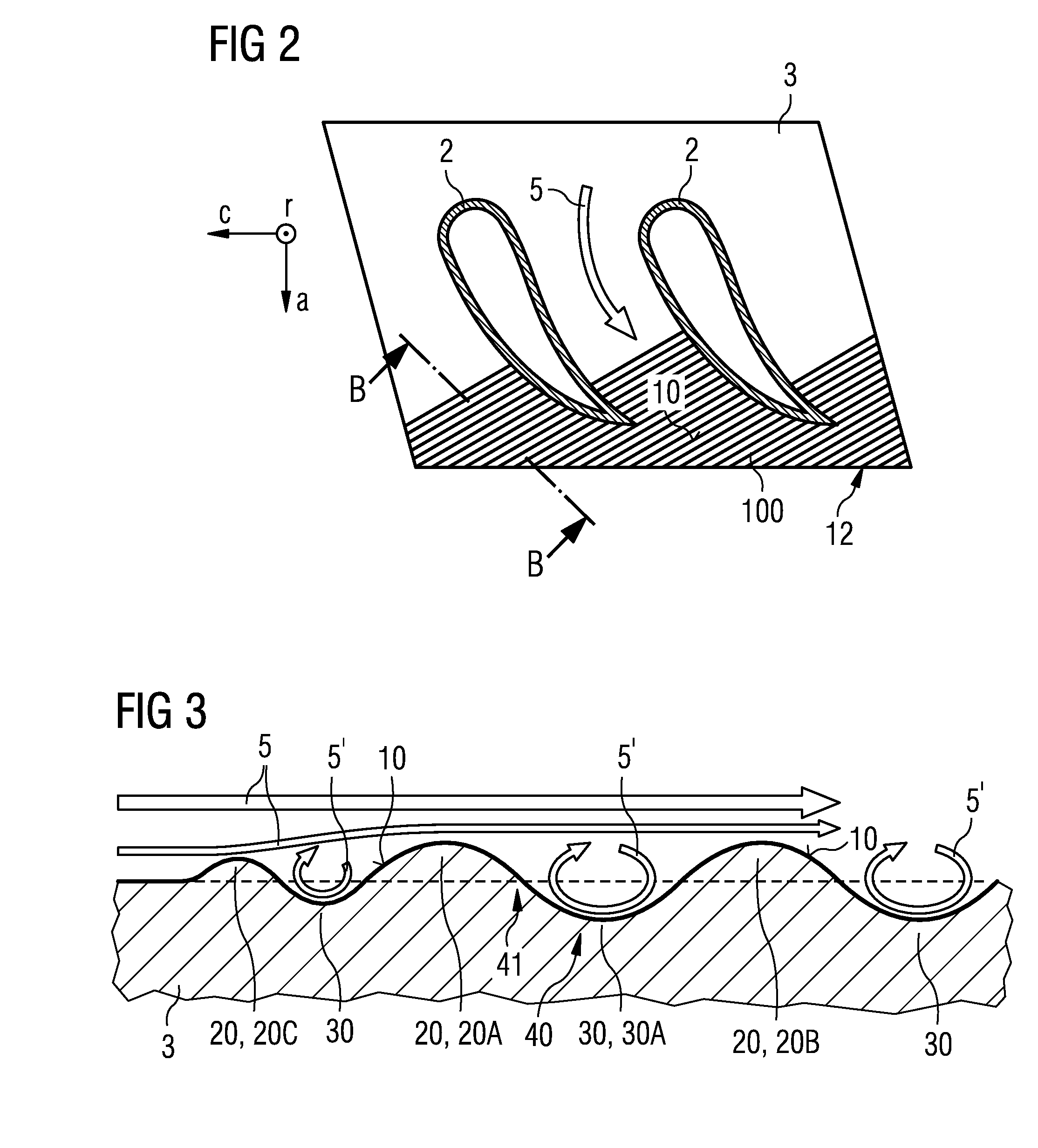
This patent is about a new design for turbo-machine components that reduces heat transfer and the need for cooling. It does this by creating a pattern of waves and valleys on the surface of the component, which creates recirculating flow pockets that slow down the fluid velocity and insulate the component from high temperature, high-velocity fluid. This design can be used with thermal barrier coating, impingement cooling, and film cooling, and may result in higher efficiency and reduced cooling requirements.

Problems solved by technology

The mentioned platform portions and other parts within the gas turbine engine may be affected by the mentioned hot fluids which again may lead to damage to these components, e.g. by oxidation.
Typically all mentioned heat resistance or cooling features may also have some negative side effects in respect of costs, efficiency, etc.
The thermal barrier coating may only be effective when there is cooling on the non flow path side, and all methods of cooling usually cause a loss of performance, because the cooling air is high pressure air typically diverted from a compressor and therefore contains some of the energy which was transferred from the compressor to the air stream.
Film cooling also may cause mixing losses when it enters the main fluid flow, as well as a reduction in the mean temperature of the main fluid flow through the turbine.

Method used


Image

  • Turbine nozzle segment and corresponding gas turbine engine
  • Turbine nozzle segment and corresponding gas turbine engine
  • Turbine nozzle segment and corresponding gas turbine engine

Examples


Embodiment Construction

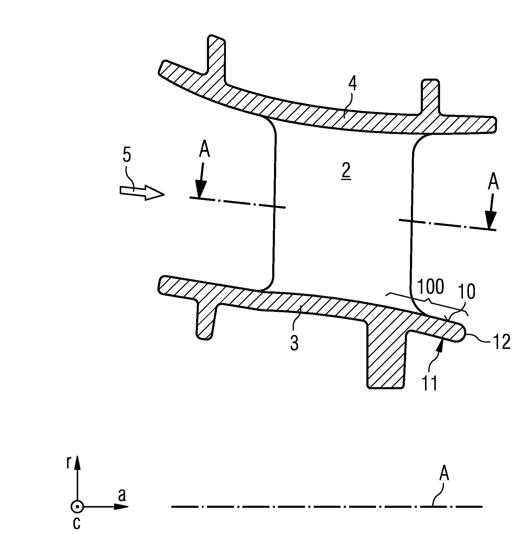
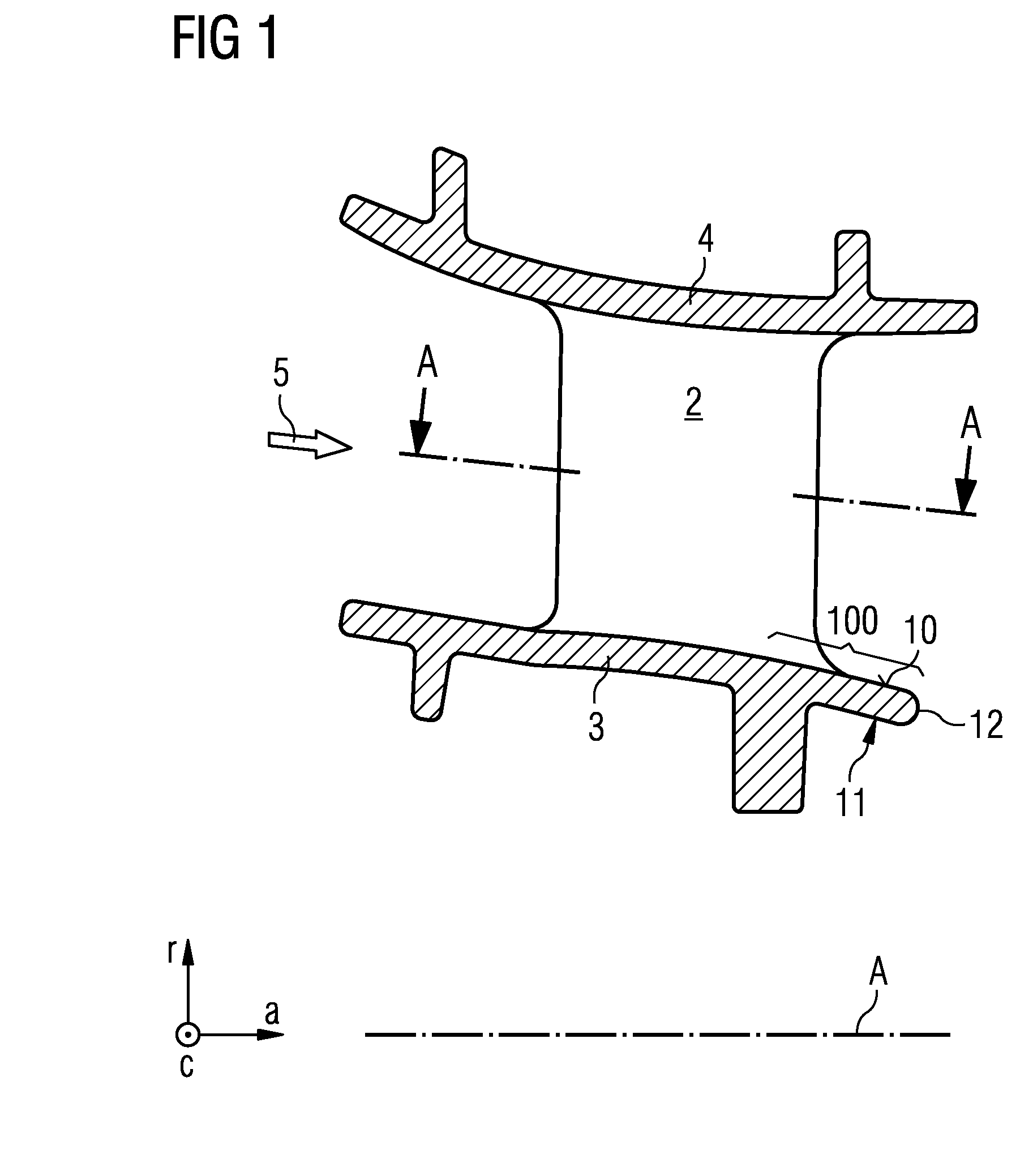
[0048]The invention will be explained be referring to a gas turbine nozzle 1 as an inventive turbo-machine component, which may be located within a turbine section of a gas turbine engine. The gas turbine nozzle 1—in fact a gas turbine nozzle segment—, as shown in FIG. 1 schematically in a cross sectional view, comprises at least one aerofoil 2, an inner platform 3, and an outer platform 4. “Inner” should be considered radially inwards, in direction of an axis A, once the gas turbine nozzle 1 is assembled into the gas turbine engine. “Outer” should be considered radially outwards.

[0049]The gas turbine nozzle 1 is particularly a stator segment which will not rotate. The aerofoil 2 is particularly a stator vane.

[0050]The gas turbine nozzle 1 may be built as a single piece, possibly by casting. A single gas turbine nozzle 1 will define a segment of an annular fluid duct. According to this embodiment a plurality of gas turbine nozzles arranged about the axis A of the turbine section of ...


PUM


Abstract

A turbine nozzle segment of a turbo-machine includes a platform defining a segment of a boundary for a main fluid path, the platform having a section, particularly a trailing section of the platform. The section has a surface along which a main fluid flows during operation of the turbo-machine. The surface further includes a plurality of alternating elevations and depressions, wherein the elevations and the depressions both are arranged substantially perpendicular to a direction of a main fluid flow of the main fluid.

Description

FIELD OF THE INVENTION[0001]The present invention relates generally to a turbo-machine component and, more specifically to an optimised flow path surface profile, e.g. of a turbine nozzle.BACKGROUND OF THE INVENTION[0002]In a gas turbine engine, hot gas is routed from at least one combustor to a turbine section, in which stator vanes are designed to direct hot combustion gases onto rotor blades resulting in a rotational movement of a rotor to which the rotor blades are connected. Typically the vanes and blades are arranged via a plurality of rows of stator vanes and rotor blades. The vanes of one row are usually identical or similar to each other and include an aerofoil portion, a radial inner platform portion and a radial outer platform portion. The platform portions form an annular passage into which the aerofoils of the stator vanes and the rotor blades extend and through which a hot fluid, heated in an upstream combustor(s), will be guided.[0003]The mentioned platform portions a...

Claims


Application Information

Patent Timeline
Patent Type & Authority Applications(United States)
IPC IPC(8): F02C7/12
CPCF02C7/12F01D5/143F01D5/145F01D9/041F05D2250/184F05D2260/22141
Inventor SHEPHERD, ANDREW
Owner SIEMENS AG
Learn More