Test device for magnetic stripe decoder chip

a magnetic stripe decoder and test device technology, applied in the field of test devices of chips, can solve the problems of low test speed, incomplete test results, time-consuming, etc., and achieve the effect of reducing test tim

Inactive Publication Date: 2013-09-19
UNIFORM INDAL CORP
View PDF27 Cites 6 Cited by
  • Summary
  • Abstract
  • Description
  • Claims
  • Application Information

AI Technical Summary

Benefits of technology

[0018]The test device for the magnetic stripe decoder chip according to the disclosure may reliably test the magnetic stripe decoder chip in various specific swiping rates, and may avoid manual swiping actions, thereby reducing the test time. Additionally, by adjusting the amplitude variation ...

Problems solved by technology

1. In order to test the reliability of the decoder chip 114a, the same decoder chip 114a should be tested repeatedly using different swiping rates and different swiping directions, which is not only time con...

Method used


Image

  • Test device for magnetic stripe decoder chip
  • Test device for magnetic stripe decoder chip
  • Test device for magnetic stripe decoder chip

Examples


Embodiment Construction

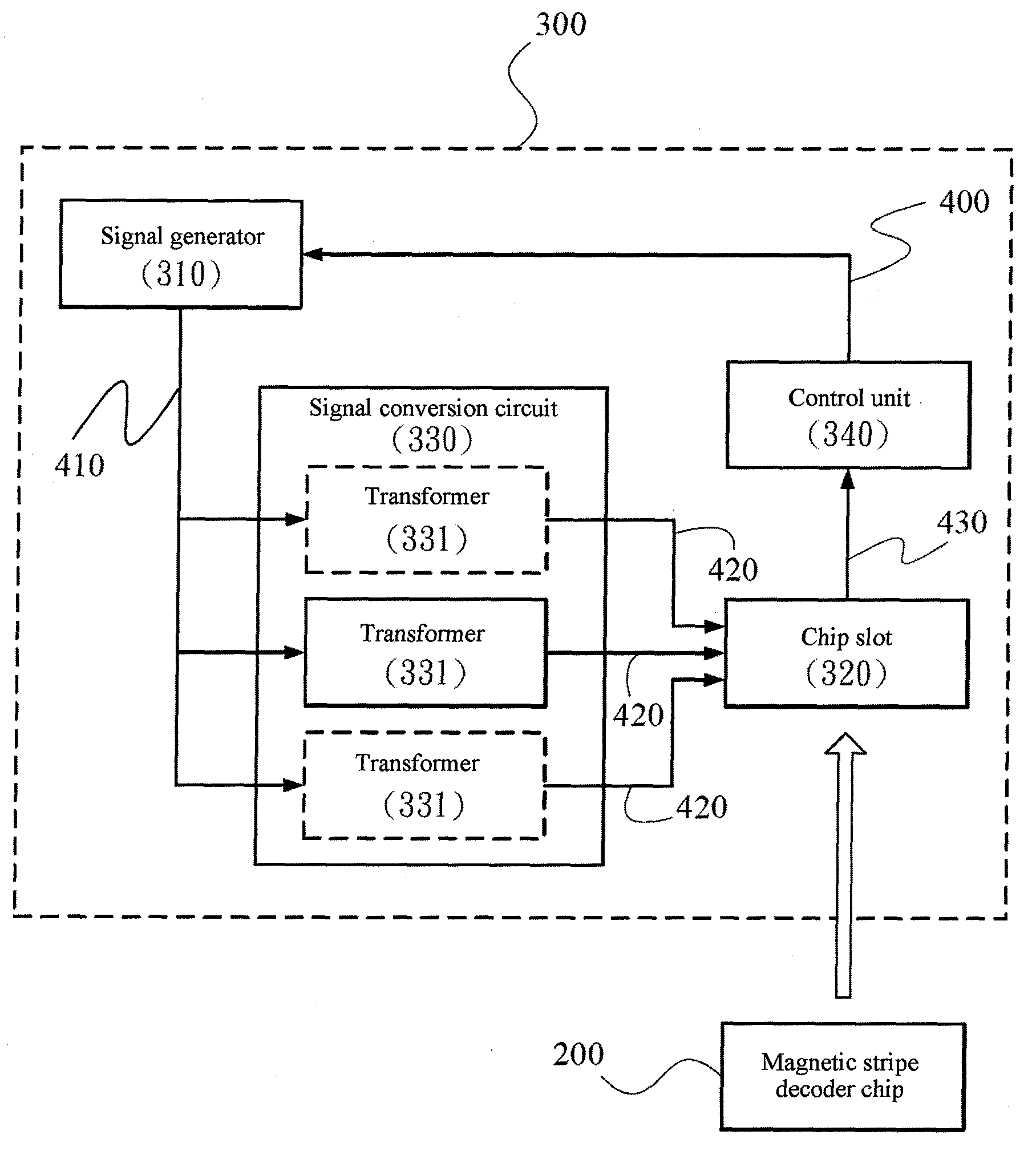
[0027]FIG. 3 is a schematic block diagram of a test device 300 for a magnetic stripe decoder chip 200 according to an embodiment.

[0028]Please refer to FIG. 3, in which the test device 300 for the magnetic stripe decoder chip 200 includes: a signal generator 310, a chip slot 320, a signal conversion circuit 330 and a control unit 340. The magnetic stripe decoder chip 200 includes at least one track signal receiving end (not shown), so as to receive a signal corresponding to a track.

[0029]The signal conversion circuit 330 is connected electrically between the signal generator 310 and the chip slot 320. The control unit 340 is connected electrically to the chip slot 320.

[0030]The signal generator 310 sequentially outputs a plurality of test waveform signals 410 (including, but not limited to, signals shown in Table 1). The test waveform signals 410 are formed by amplifying or reducing a period of a basic track signal 400 in different magnifications (as shown in FIG. 4). The chip slot 3...


PUM


Abstract

A test device for a magnetic stripe decoder chip includes a signal generator, a chip slot, a signal conversion circuit and a control unit. The signal generator sequentially outputs a plurality of test waveform signals. The signal conversion circuit includes at least one transformer, the transformer is used for converting the test waveform signals into a plurality of false track signals, and correspondingly outputting the false track signals to one of track signal receiving ends of the magnetic stripe decoder chip. The control unit receives at least one decoding string generated respectively by decoding the false track signals through the magnetic stripe decoder chip, and compares the at least one decoding string with a test string represented by the basic track signal, thereby determining a decoding function of the magnetic stripe decoder chip.

Description

CROSS-REFERENCES TO RELATED APPLICATIONS[0001]This non-provisional application claims priority under 35 U.S.C. §119(a) on Patent Application No. 101204634 filed in Taiwan, R.O.C. on 2012 Mar.3 14, the entire contents of which are hereby incorporated by reference.BACKGROUND[0002]1. Technical Field[0003]The disclosure relates to a test device of a chip, and more particularly, to a test device for a magnetic stripe decoder chip.[0004]2. Related Art[0005]FIG. 1 is a relation diagram of a magnetic stripe and a decoding signal in the prior art. Generally, for a magnetic stripe 101a on a financial card or a credit card, specifically coded binary data is corresponding to a sorting and distribution situation of magnetic poles on the magnetic stripe. The magnetic stripe may record information using coding techniques such as a frequency modulation (FM) technique, a phase modulation (PM) technique, and a dual-frequency coherent phase (F / 2F, or Aiken Biphase), technique. The drawing shows an exa...

Claims


Application Information

Patent Timeline
IPC IPC(8): G06K7/00
CPCG01R31/2829G06K7/0095G01R31/2848
Inventor HSU, TUNG-JUNG
Owner UNIFORM INDAL CORP
Why Eureka
Try Eureka