Reconfigurable Radiating Phase-Shifting Cell Based on Complementary Slot and Microstrip Resonances

a phase-shifting cell and complementary slot technology, applied in the field of reconfigurable radiating phase-shifting cells, can solve the problems of difficult to obtain the phase state with little resonance of the cell, significant losses, and inability to optimize so as to reduce the frequency variation of the wave, reduce the resonant character of the cell, and be more linear.

Active Publication Date: 2013-09-19
THALES SA +2
View PDF3 Cites 7 Cited by
  • Summary
  • Abstract
  • Description
  • Claims
  • Application Information

AI Technical Summary

Benefits of technology

[0011]One aim of the invention is to provide a phase-shifting cell with variable and controlled localized loads (micro-switches) allowing a phase-shift range to be covered with a reduced frequency variation of the p...

Problems solved by technology

The mesh size of the reflector array, in other words the spatial periodicity according to which the cells are arranged in an array, is therefore much greater than 0.5 λ. This results in a non-optimal behaviour for very oblique incidences of the wave, associated with the possibility of excitation of a higher-order Floquet mode.
Although it is possible to prod...

Method used


Image

  • Reconfigurable Radiating Phase-Shifting Cell Based on Complementary Slot and Microstrip Resonances
  • Reconfigurable Radiating Phase-Shifting Cell Based on Complementary Slot and Microstrip Resonances
  • Reconfigurable Radiating Phase-Shifting Cell Based on Complementary Slot and Microstrip Resonances

Examples


first embodiment

[0079]In a first embodiment, illustrated in FIG. 8a, the panel is composed of a multilayer dielectric substrate on whose front face the radiofrequency (RF) chips that comprise the metal pattern of the cell and the MEMS are mounted. These RF chips are then referred to as monolithic chips and, for example, made of quartz, fused silica or alumina. The dielectric substrate, made for example of RO 4003, performs the function of a spacer between the RF chips 803 and the ground plane, and enables the through-connection of the control signals to the DC chips mounted on the back face of the substrate. The routing of the control signals on the front face is then carried out within the RF chips. Microelectronics processing can be used in order to form the resistive lines, at least in sections, at the place where these lines meet slots.

second embodiment

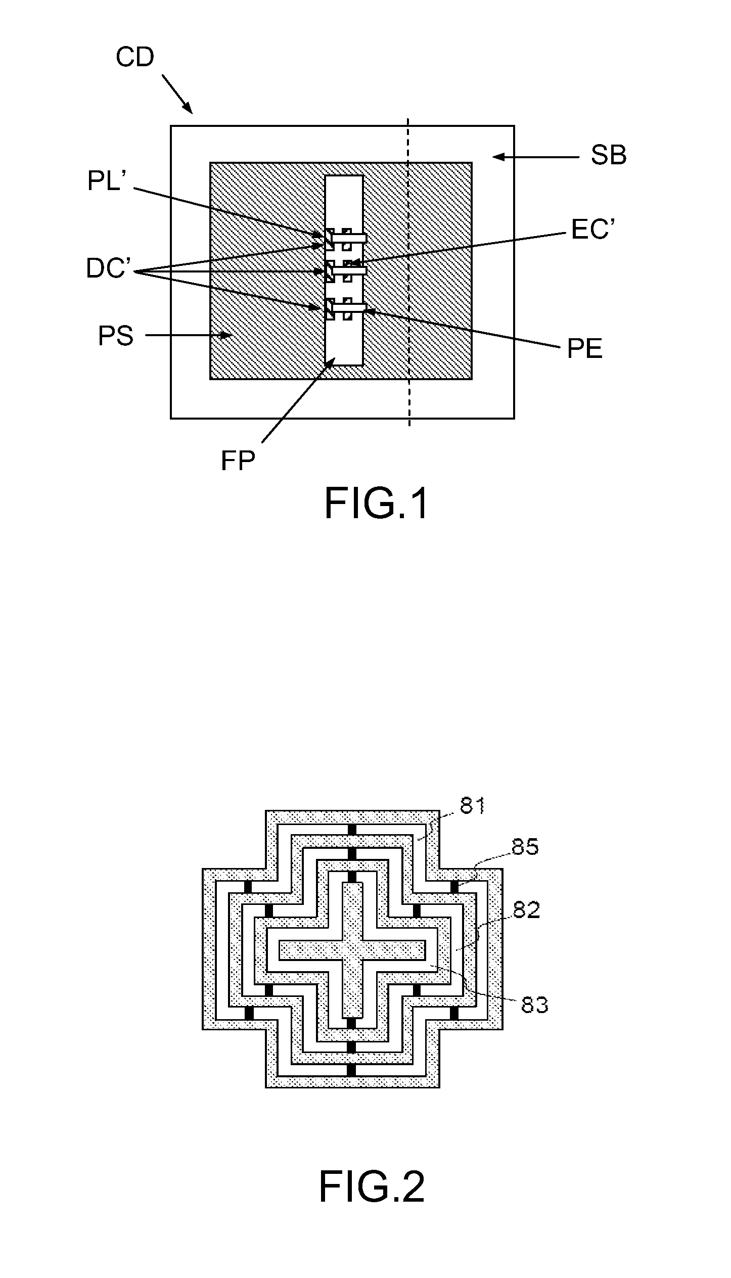
[0080]In a second embodiment illustrated in FIG. 8b, the panel is composed of a multilayer dielectric substrate on which the metal pattern 851 of the cell is etched, and on which MEMS components 853 are mounted; this is then a hybrid design.

[0081]As illustrated in FIG. 9, control vias 901 can be disposed at the periphery of the cell (within the frame 908), or at its centre, without fundamentally altering its operation. In addition, the periodic arrangement of metal through vias on the periphery could have the same effect as a peripheral metal wall connecting the frame 908 and the ground plane. Several of these vias could then be used for routing control signals from the back face to the front face. It is also possible to connect the central patch of the cell 903 to the ground plane by a metal through via without significantly modifying its electrical behaviour. A control via 902 can therefore also be installed at this location. When this via is used for the control, it must be insul...


PUM


Abstract

A radiating phase-shifting cell is designed to favour the excitation of an equivalent resonance of the “slot” type in a first part of the phase cycle, and to favour an equivalent resonance of the “microstrip” type in a second part of the phase cycle. This property notably allows the bandwidth of the phase-shifting cells to be optimized. A phase range of 360° can in effect be segmented into two sub-ranges of around 180°. This segmentation into two sub-ranges is made possible by the complementarity of the resonant modes of the slot or microstrip type. The radiating phase-shifting cell is notably applicable to reflector arrays for an antenna designed to be installed on a space craft such as a telecommunications satellite or on a terrestrial terminal for satellite telecommunications or broadcasting systems.

Description

CROSS-REFERENCE TO RELATED APPLICATION[0001]This application claims priority to foreign French patent application No. FR 1102786, filed on Sep. 14, 2011, the disclosure of which is incorporated by reference in its entirety.FIELD OF THE INVENTION[0002]The field of the invention is that of reconfigurable radiating phase-shifting cells. It is notably applicable to reflector arrays for an antenna designed to be installed on a space vehicle such as a telecommunications satellite or on a terrestrial terminal for satellite telecommunications or broadcasting systems.BACKGROUND[0003]An antenna reflector array (or ‘reflectarray antenna’) comprises a set of radiating phase-shifting cells assembled in a one- or two-dimensional array and forming a reflecting surface allowing the directivity and gain of the antenna to be increased. The radiating phase-shifting cells of the reflector array, of the metal patch type and / or slot type, are defined by parameters able to vary from one cell to another, t...

Claims


Application Information

Patent Timeline
IPC IPC(8): H01Q3/36
CPCH01Q3/36H01Q3/46H01P1/18
Inventor LEGAY, HERVEGIRARD, ETIENNEBRESCIANI, DANIELEGILLARD, RAPHAELSALTI, HASSANMAKDISSY, TONYFOURN, ERWAN
Owner THALES SA
Why Eureka
Try Eureka