
Ultrasound imaging method/technique for speckle reduction/suppression in an improved ultra sound imaging system

an ultra sound imaging and ultra sound technology, applied in image enhancement, image analysis, instruments, etc., can solve the problems of reducing the utility of some medical diagnostic applications, affecting the image quality of medical ultrasound imaging systems, and reducing the amount of data to be handled, so as to reduce the loss of information

Inactive Publication Date: 2013-09-19
INDIAN INST OF TECH
View PDF22 Cites 18 Cited by
  • Summary
  • Abstract
  • Description
  • Claims
  • Application Information

AI Technical Summary

Benefits of technology

This patent describes an improved method and system for reducing speckle in ultrasound imaging. The method involves processing raw data samples to convert them to pixel values and reduce speckle noise. The system includes a transducer, transmitter, receiver, time gain compensation, A / D, demodulator, envelope detection, log compression, pre-processing, processor, and display. The system simultaneously performs speckle reduction and scan conversion, providing a speckle filtered output image. The technical effects of this patent are improved image quality and more accurate data analysis.

Problems solved by technology

But the resolutions and speckle noises are the dominant issues, which reduces its utility in some medical diagnostics applications.
But in this case, the amount of data to be handled is larger.
Unfortunately, the image quality of medical ultrasound imaging system is limited by some physical phenomena underlying in the acquisition system.
Speckle noise generated in the image is one such limitation.
It degrades the resolutions, contrast and obscures the underlying anatomy and makes human interpretation and computer-assisted detection techniques difficult and inconsistent as disclosed in Michailovich Oleg V. Tannenbaum Allen, “Despeckling of Medical Ultrasound Images”, IEEE Trans. on Ultrasonics Ferroelectrics and Frequency Control, Vol. 53, No. 1, pp.
Hence, reduction of speckles is one of the most important challenges to the ultrasound system designers'.
However, all these compounding techniques suffers from different limitations:They suffer from loss of temporal and / or spatial resolution.Clinical application of strain compounding is limitedContrast resolution for small objects may be degraded.Complexity of the system increases.
The main limitation of the Bamber, Dutt, and Lee filters is that the use of too large window introduces a loss of fine details in the image.
On the other hand, the use of small window implies insufficient speckle suppression homogeneous region.
However, their computational complexity is large.
These methods have one common limitation in retaining subtle features such as small cysts and lesions in ultrasound images.
The main challenge of wavelet denoising is the proper choice of shrinkage function and the threshold.
So the UT tends to be high for large values of n, killing many signal coefficients along with the noise.
Thus, the threshold does not adapt well to discontinuities in the signal.
Two major limitations of transform domain shrinkage methods are that they exhibit (a) pseudo-Gibbs and (b) fake feature types of artifacts in images corrupted with medium to high levels of noise.
The problem of this method is the selection of the constant c and the center weight w(K+1, K+1), which influence the results.
The ultrasound power emitted from the transducer elements is not spatially uniform, and the multiple echoes reduce speckle in the image.
The drawbacks of the above mentioned prior art is that the amount of data to be handled during speckle reduction is large and thus increases complexity.
Furthermore, after noise reduction from raw data, interpolation is to be done for scan conversion, which further increases complexity.
The interpolation stage in the prior art increases the loss of information and does not provide better output image quality.
The prior art systems and method cannot be used with SR (super resolution) ultrasound image reconstruction techniques.
The drawback of this conventional procedure is that the interpolation in the scan conversion stage makes the noise more coloured and the effect of noise is spread from a smaller region to relatively bigger region.
Moreover, we lose some information in the scan conversion process due to low pass nature of interpolation operation.
This degrades the performance of the conventional procedure.

Method used


Image

  • Ultrasound imaging method/technique for speckle reduction/suppression in an improved ultra sound imaging system
  • Ultrasound imaging method/technique for speckle reduction/suppression in an improved ultra sound imaging system
  • Ultrasound imaging method/technique for speckle reduction/suppression in an improved ultra sound imaging system

Examples


first embodiment

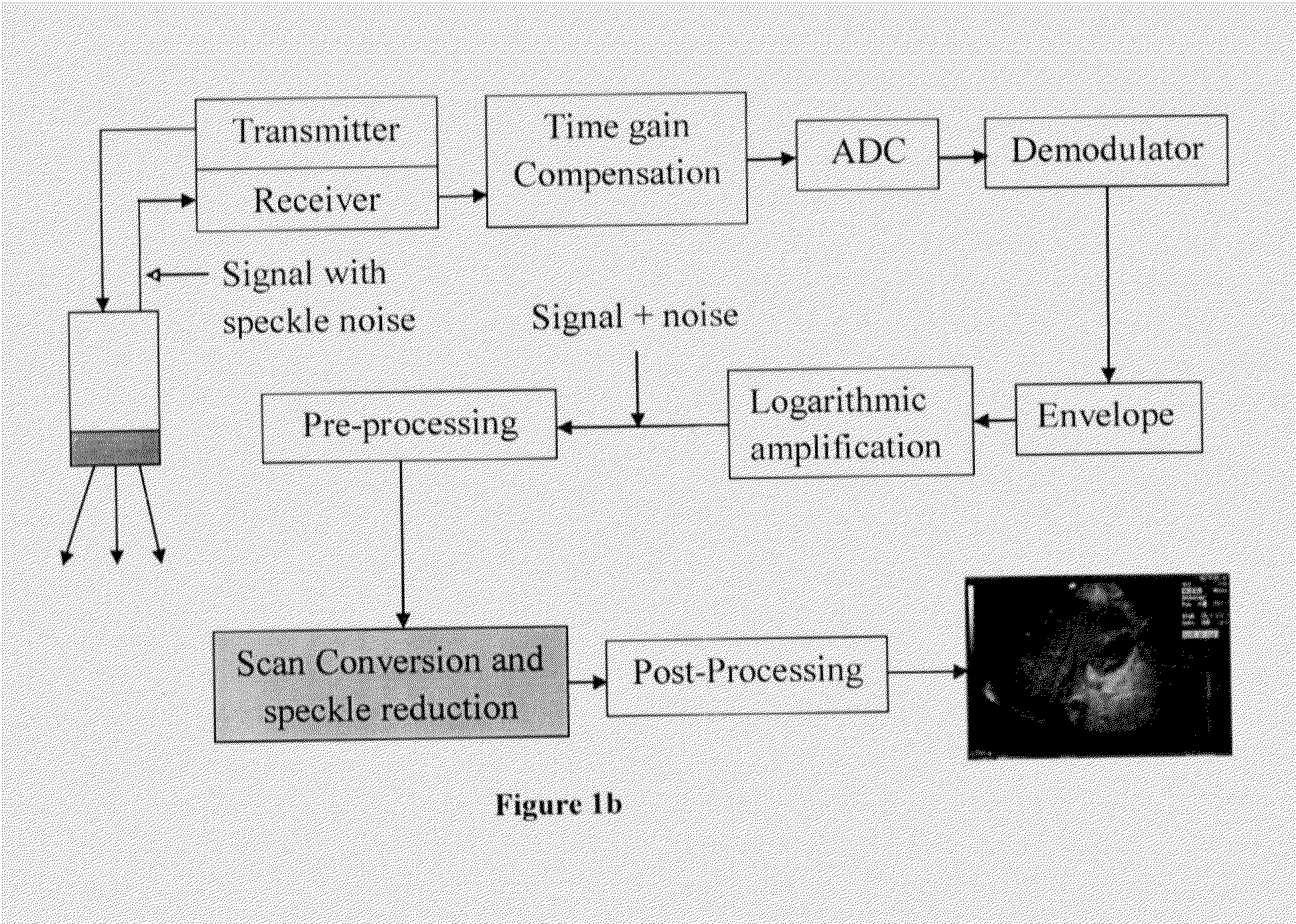
[0126]According to the present invention there is provided an improved method for speckle reduction in an ultrasound imaging system. The method comprising steps of receiving in a processor means raw data samples as an input comprising image signals with noises from a logarithmic amplifier, processing the received image signals for scan conversion and speckle reduction in the processor means so as to get pixel value from the raw data samples and to perform speckle reduction so as to provide speckle filtered output image.

[0127]The speckle reduction and scan conversion are performed / processed simultaneously. The pixel values at a raster grid points in a rectangular co-ordinate system are determined using filtering technique / speckle reduction technique by means of speckle reduction filter.

[0128]Further the step of processing / computation of the pixel value from the raw data as disclosed above comprises steps of determining plurality of radial lines in the rectangular co-ordinate system, ...

second embodiment

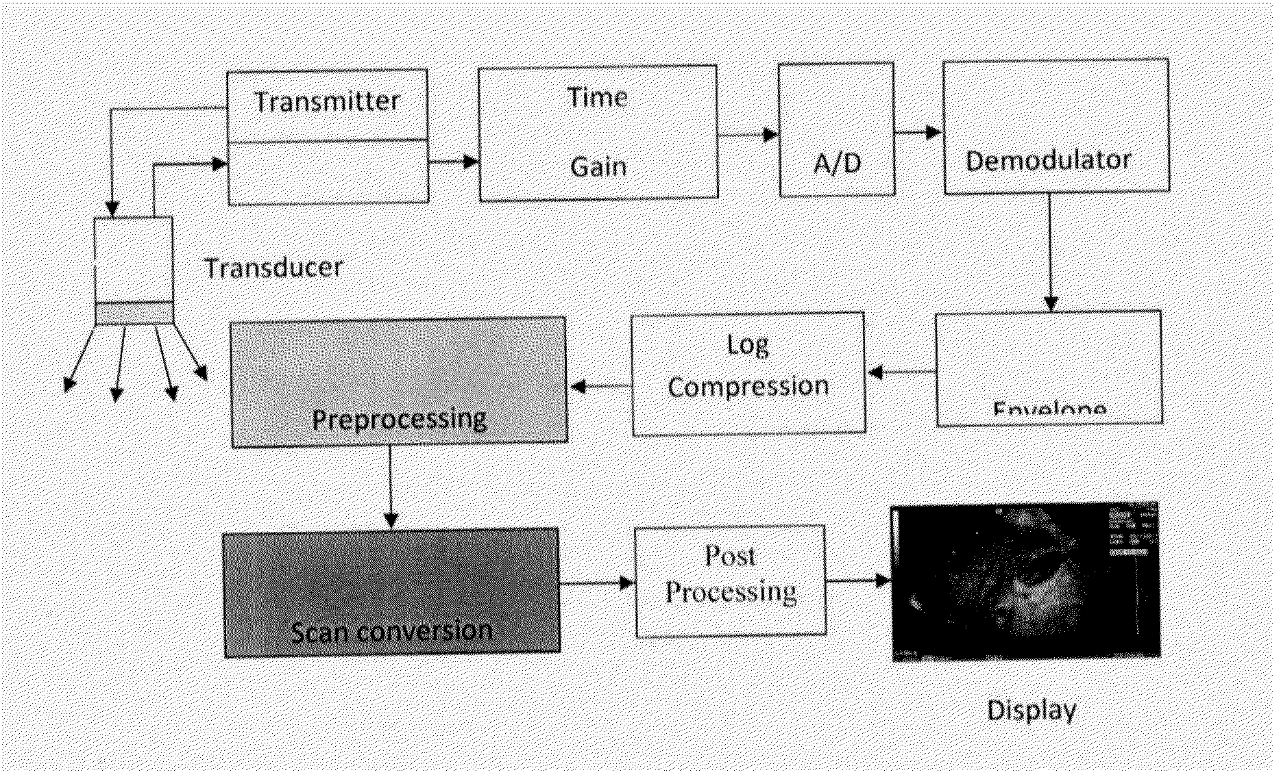
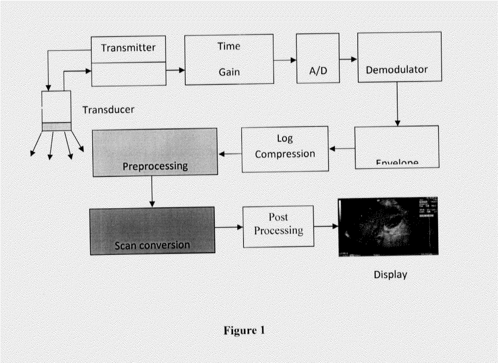
[0141]According to the present invention there is provided an improved ultra sound imaging system for speckle reduction. the system comprises a transducer means, a transmitter means operatively connected with the transducer means, a receiver means operatively connected with the a transducer means to get raw data / signal with speckle noise, a time gain compensation means operatively connected with the receiver means, a A / D means operatively connected with the time gain compensation means, a demodulator means operatively connected with the A / D means to provide demodulated data as output from the raw data, an envelope means operatively connected with the demodulator means comprises envelope detected raw scan data, a log compression means / logarithm amplification operatively connected with the envelope means to transform the envelope detected raw scan data to log compressed data, a pre-processing means operatively connected with the log compression means, a processor means operatively con...


PUM


Abstract

The present invention relates to an improved ultrasound imaging method / technique for speckle reduction / suppression in an ultra sound imaging system in which scan conversion and speckle reduction is performed simultaneously in the scan conversion stage avoiding any kind of conventional interpolation. An improved method for speckle reduction in an ultrasound imaging system and an improved ultra sound imaging system for speckle reduction is provided in the present invention. The method comprises steps of receiving in a processor means raw data samples as an input comprising image signals with noises from a logarithmic amplifier, processing the received image signals for scan conversion and speckle reduction in the processor means so as to get pixel value from the raw data samples and to perform speckle reduction so as to provide speckle filtered output image.

Description

[0001]The present invention relates to an improved method for speckle reduction / suppression in an ultra sound imaging system. Particularly, the present invention relates to improved method for speckle reduction where the speckle reduction and scan conversion are performed simultaneously or the speckle reduction is done before scan conversion, preferably speckle reduction and scan conversion being performed simultaneously. More particularly, the present invention relates to an improved method for speckle reduction using an improved filter in said ultra sound imaging system. The invention also relates to an improved ultra sound imaging system having reduced speckles. Further the present invention also includes improved filter for improved speckle reduction in ultra sound imaging system.BACKGROUND OF THE INVENTION[0002]Ultrasound imaging has got immense importance as diagnostic tool in medical applications for its low cost and non-invasive imaging modality. But the resolutions and spec...

Claims


Application Information

Patent Timeline
IPC IPC(8): G06T5/00
CPCG01S7/52044G06T2207/10132G06T5/002G01S7/52077G06T5/70G01S7/52G01S15/89
Inventor NANDI, DEBASHISMUKHOPADHYAY, SUDIPTA
Owner INDIAN INST OF TECH
Learn More