Energy-efficient and reliable operation of a vacuum waste collection system

a vacuum waste collection and reliable technology, applied in the field of waste management and waste disposal, can solve the problems of shutting down an entire branch line or transport line, affecting the efficiency of the system, so as to achieve energy-efficient and reliable effects

Active Publication Date: 2013-09-19
EHNVAK AB
View PDF7 Cites 10 Cited by
  • Summary
  • Abstract
  • Description
  • Claims
  • Application Information

AI Technical Summary

Benefits of technology

[0014]It is a general object of the present invention to provide an improved method of operating a vacuum waste collection system as well as an energy-efficient and reliable vacuum waste collection system.
[0020]In this way, energy-efficient operation of the vacuum waste collection system is obtained, where a much larger portion of the air flow is seized for transport of waste compared to conventional collection procedures.
[0021]It is possible to reduce the overall collection time and energy consumption by collectively transporting waste downstream towards the central collection point.
[0022]By using detector means in the transport pipe system it is possible to ensure, for each branch except the last, that the accumulated waste is transported past an intersection to the next branch so that no or only insignificant amounts of remaining waste are left in the transport pipe system upstream relative to the intersection to the next branch. In this way, the risk for blockage in the transport pipe system is avoided or at least minimized.
[0023]The so-called post-suction time is significantly reduced compared to a situation when the waste of each branch is individually transported all the way to central collection point. With the invention, waste in a branch only needs to be transported past the intersection to the next branch, and then the collection procedure can continue with the next branch.

Problems solved by technology

Attempts have been made to reduce the emptying and collection times by increasing the vacuum in the transport pipes of the system, but unfortunately such an increase of the vacuum will increase the danger of compacting the waste too much, resulting in a plug flow that may cause blockage in the pipes of the system.
Such blockage may even shut down an entire branch line or transport line.
Another problem related to the employment of increased vacuum levels is the noise that is generated by the resulting airflow through the waste chute in connection with the emptying.
In addition, high levels of vacuum may force opened access ports to close rapidly and jam or even injure a person that is about to discharge a bag of waste.
In larger and more complex systems however, level-controlled emptying tends to have an opposite effect, leading to frequent jumps between different branches of the system and thus inefficient use of the available waste collection resources.
Conventional level-controlled emptying is also inflexible in that once the level sensors have been arranged in the waste chutes, it is difficult to flexibly adapt the predefined levels so as to change the time margins of the vacuum waste collection system and optimize the operation of the system.
The predefined level used in conventional level-controlled emptying may be too high to prevent overloading of waste chutes at high load in the system, whereas at low load in the system, the predefined level may be too low for optimal utilization of the resources.
Another disadvantage is that the “first-come first-serve” principle does not consider the consequences of the order in which the waste chutes are emptied.
For example, there is always the risk of overloading of a waste chute in a critical area, which is not first in the emptying queue.

Method used


Image

  • Energy-efficient and reliable operation of a vacuum waste collection system
  • Energy-efficient and reliable operation of a vacuum waste collection system
  • Energy-efficient and reliable operation of a vacuum waste collection system

Examples


Embodiment Construction

[0043]Throughout the drawings, the same reference characters will be used for corresponding or similar elements.

[0044]In order to avoid misconceptions, it should be understood that the term ‘waste’ not only includes what traditionally is denoted as ‘household waste’ or ‘household garbage’ but also includes all fractions within the field of waste disposal such as, but not limited to paper, clothes, laundry, packages and organic waste.

[0045]For a better understanding of the invention, a general overview of an example of a vacuum waste collection system will now be made with reference to FIG. 1.

Example System Overview

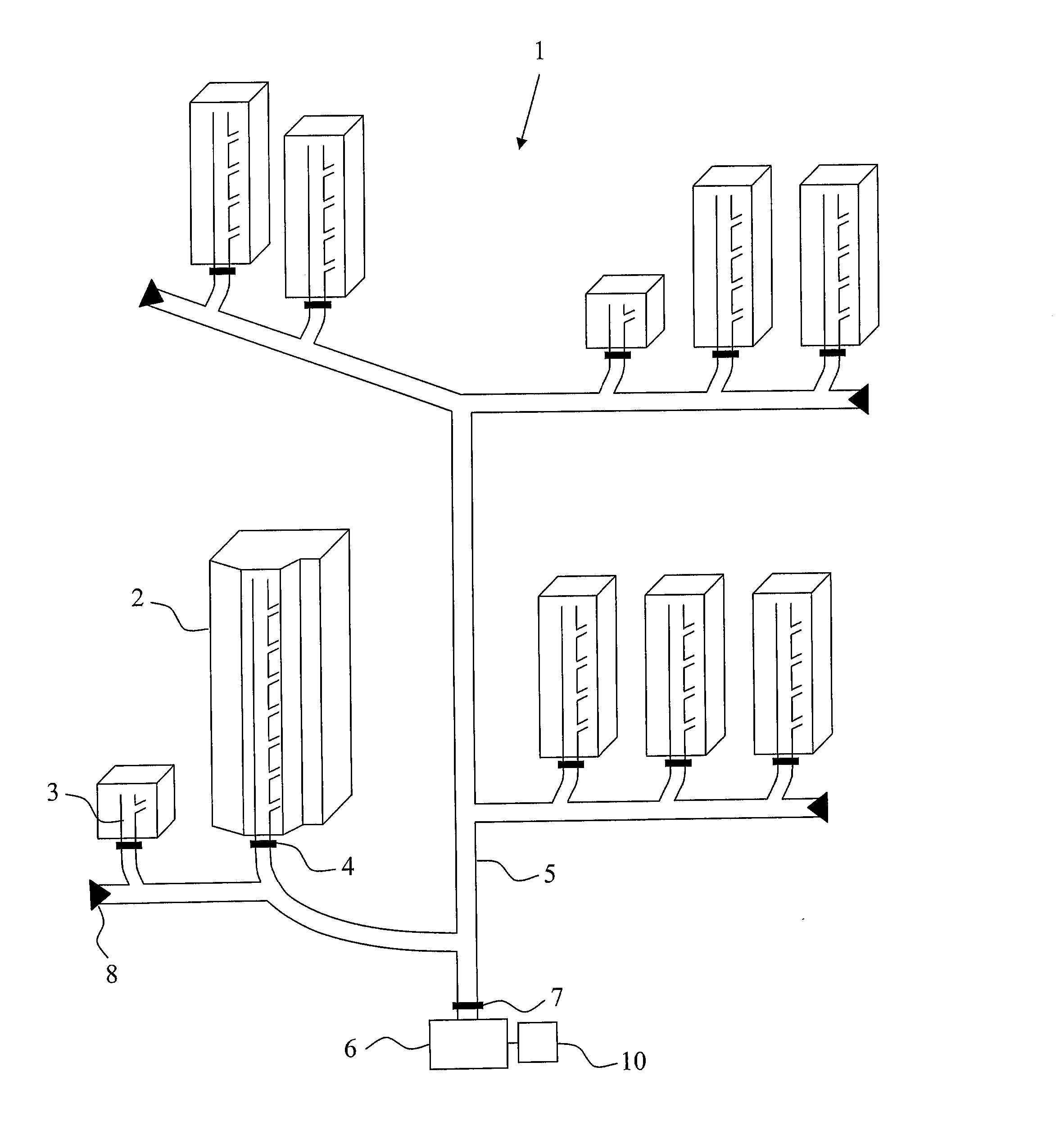
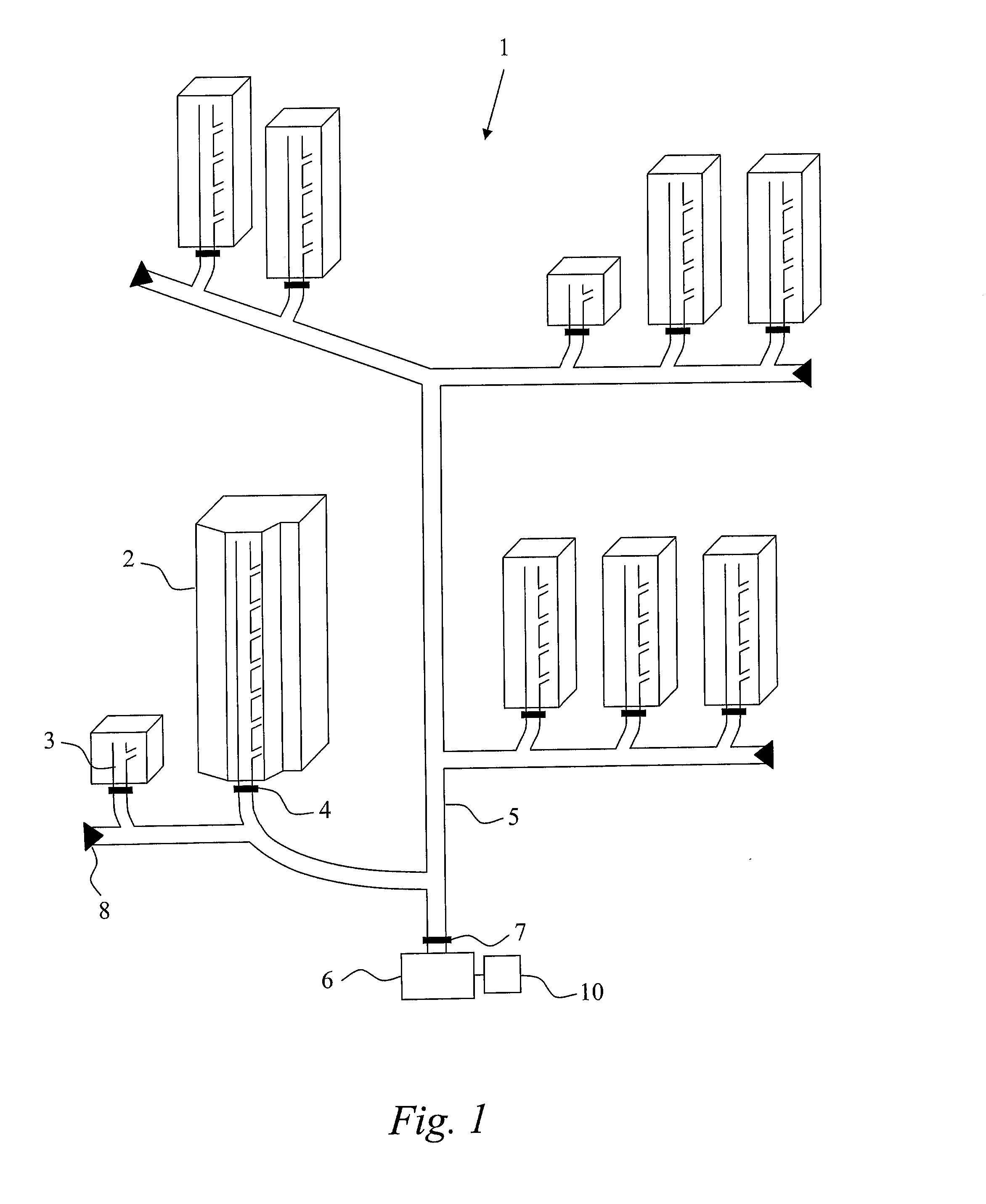
[0046]FIG. 1 is a schematic drawing illustrating an example of a vacuum waste collection system. As an example, assume that the vacuum waste collection system 1 is installed in a residential and / or business area having a number of buildings. Each building 2 is installed with a waste chute 3, or equivalent. In this particular example, the waste chutes are vertical chutes ex...


PUM


Abstract

Vacuum waste collection system is provided (1a) by successively selecting a number of branches in a sequence for emptying and transport of waste, wherein the intersection (1, 2, 3, 4) of each next branch in the sequence is at the same o shorter transport distance to a central waste collection point (6) compared to the intersection (1, 2, 3, 4) of the previous branch in the sequence, and collectively transporting accumulated waste from the selected branches towards the central waste collection point (6) by successively operating the air inlet valves (av1, av2, av3, av4, av5) of the corresponding branches. For each selected branch except the last branch, accumulated waste is transported towards the central collection point (6) by causing the corresponding air inlet valve (av1, av2, av3, av4, av5) to be open until it is detected by detector means (WO) in the transport pipe system that the waste has been transported past an intersection (1, 2, 3, 4) to the next branch, and then changing to the next branch For the last branch, accumulated waste is transported to the central waste collection point (6).

Description

TECHNICAL FIELD OF THE INVENTION[0001]The present invention generally relates to waste management and waste disposal, and more particularly to a method of operating a vacuum waste collection system, a vacuum waste collection system, a control system as well as a computer program product for controlling operation of a vacuum waste collection system.BACKGROUND OF THE INVENTION[0002]Waste collection systems operating at sub-atmospheric or vacuum pressure for transport of waste by means of suction of air have been in use for many years and are well known to present an efficient, clean and convenient solution to the waste disposal problem. Such systems for suction transport of waste, hereinafter simply referred to as vacuum waste collection systems, have worked remarkably well in smaller and medium-sized residential and office building areas. However, as vacuum waste collection systems have been placed into service in larger and more dense residential and office building areas and / or are...

Claims


Application Information

Patent Timeline
Patent Type & Authority Applications(United States)
IPC IPC(8): B65G51/00
CPCB65G51/00B65F5/005B65G51/02B65G53/24B65G53/34B65G53/40B65G53/52B65G53/56B65G53/66B65G2201/0238B65G2812/16
Inventor ARRABAL, DAVID GONZALEZFORESTIER, NIKLAS MATTIAS
Owner EHNVAK AB
Why Eureka
Try Eureka