
Cable connector and endoscope apparatus

a technology of endoscope and cable connector, which is applied in the direction of fixed connections, application, coupling device connections, etc., can solve the problems of difficult maintenance of the endoscope apparatus, difficult to connect each one of the electric lines in the cable structure to the control unit, and extreme disposed of conductive lands, etc., to achieve safe and easy transmission operation

Active Publication Date: 2013-09-19
FUJIFILM CORP
View PDF0 Cites 45 Cited by
  • Summary
  • Abstract
  • Description
  • Claims
  • Application Information

AI Technical Summary

Benefits of technology

The present invention provides a cable connector and an endoscope apparatus that allows for a high number of electric lines to be connected safely and easily without any issues with transmission. The cable structure has a simplified structure, with the first and second land patterns placed separately for efficient electrical coupling. The circuit board has cutouts to prevent interference with the connection and a tab portion to enable safe passage of the circuit board through the elongated tube. This results in a more reliable and efficient electrical connection for transmitting data.

Problems solved by technology

It is extremely difficult to connect each one of the electric lines in the cable structure to the control unit after passage through the flexible tube device.
If the electric lines are connected with a mechanical part with a larger width than an inner diameter of the elongated tube, maintenance of the endoscope apparatus is very hard.
There arises a problem in which conductive lands are disposed extremely close to each other.
Difficulty in coupling the electric lines to the conductive lands is very high.
Thus, breakage of lines, short-circuiting and electric noise are likely to occur seriously.
If the number of the electric lines for connection to the cable connector is lowered and the number of the cable connector is increased for safe disposition of the conductive lines or conductive lands, then another problem arises in low operability in mounting the cable structure in the flexible tube device of the elongated tube.

Method used


Image

  • Cable connector and endoscope apparatus
  • Cable connector and endoscope apparatus
  • Cable connector and endoscope apparatus

Examples


Embodiment Construction

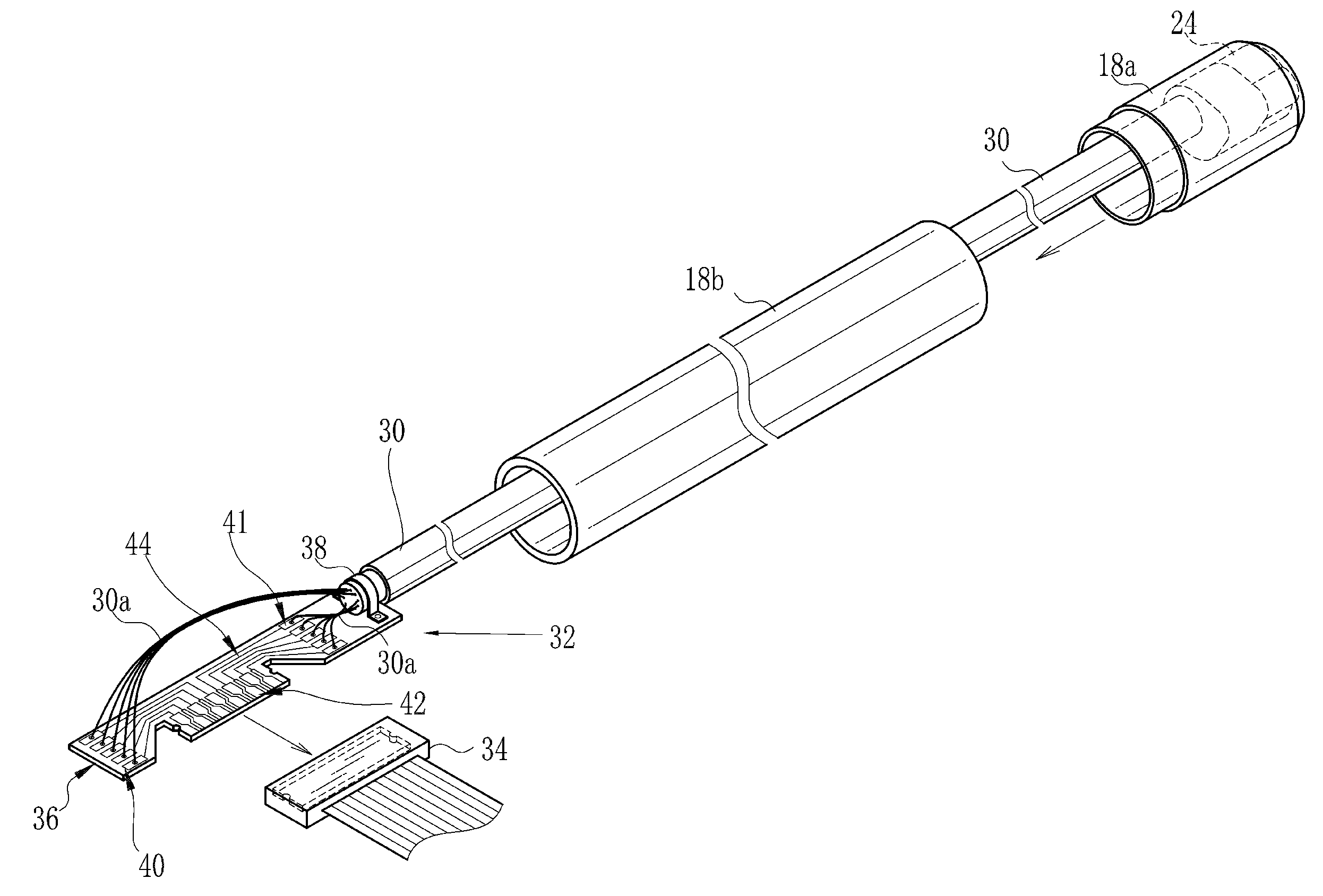
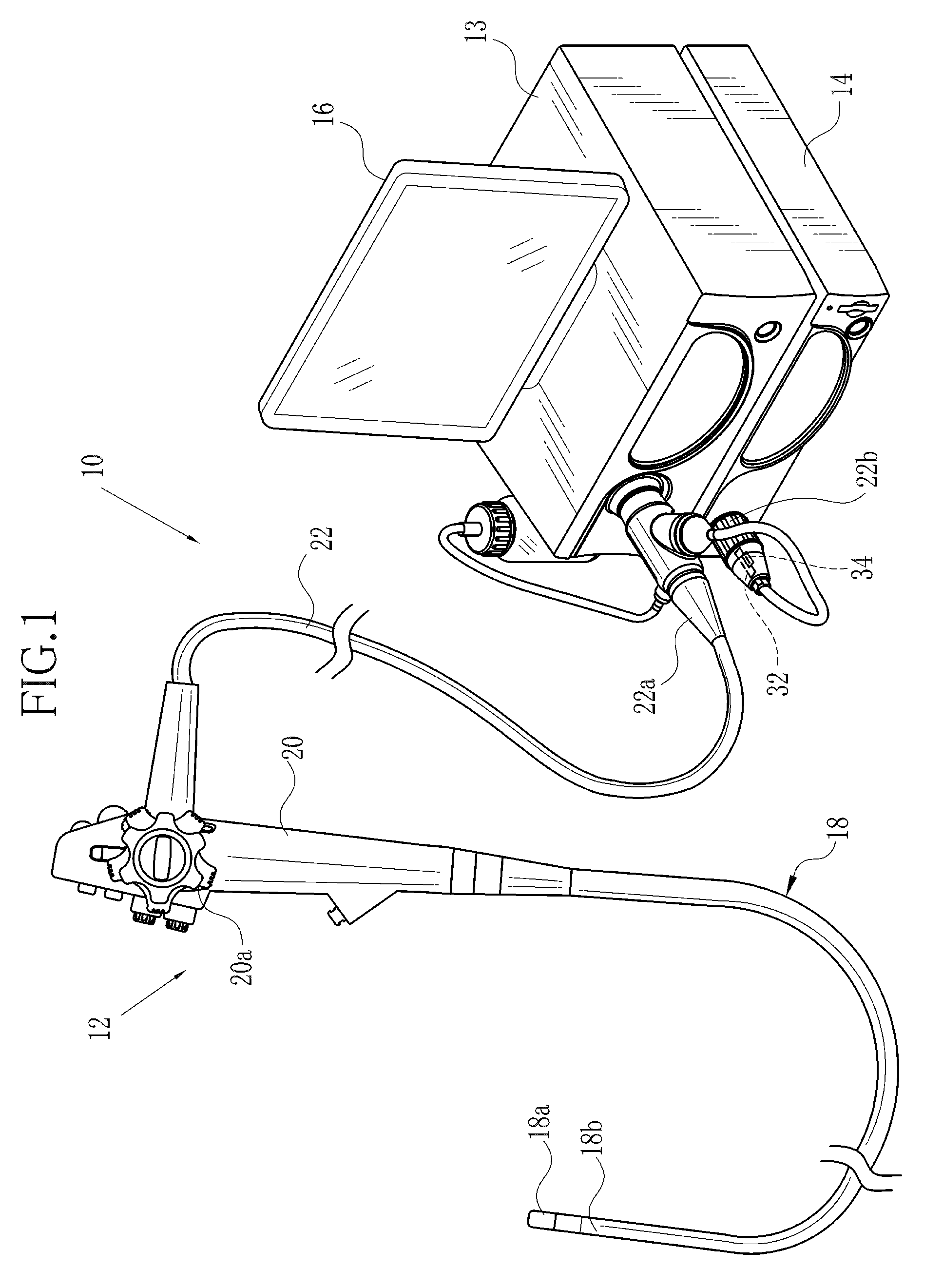
[0060]In FIG. 1, an endoscope system 10 includes an electronic endoscope apparatus 12, a light source apparatus 13, a processing apparatus 14 and a monitor display panel 16. The endoscope apparatus 12 includes an elongated tube 18 and a handle device 20. The elongated tube 18 is entered in a body cavity of a patient, for example, gastrointestinal tract. The handle device 20 is disposed at a proximal end of the elongated tube 18. A universal cord device 22 extends from the handle device 20 for connection to the light source apparatus 13 and the processing apparatus 14.

[0061]A light source is incorporated in the light source apparatus 13. The elongated tube 18 has a tip device 18a. Light from the light source is guided by a light guide device extending through the universal cord device 22, the handle device 20 and the elongated tube 18 toward the tip device 18a, which emits the light in a distal direction.

[0062]A camera module 24 as circuit device or electrical device is incorporated ...


PUM


Abstract

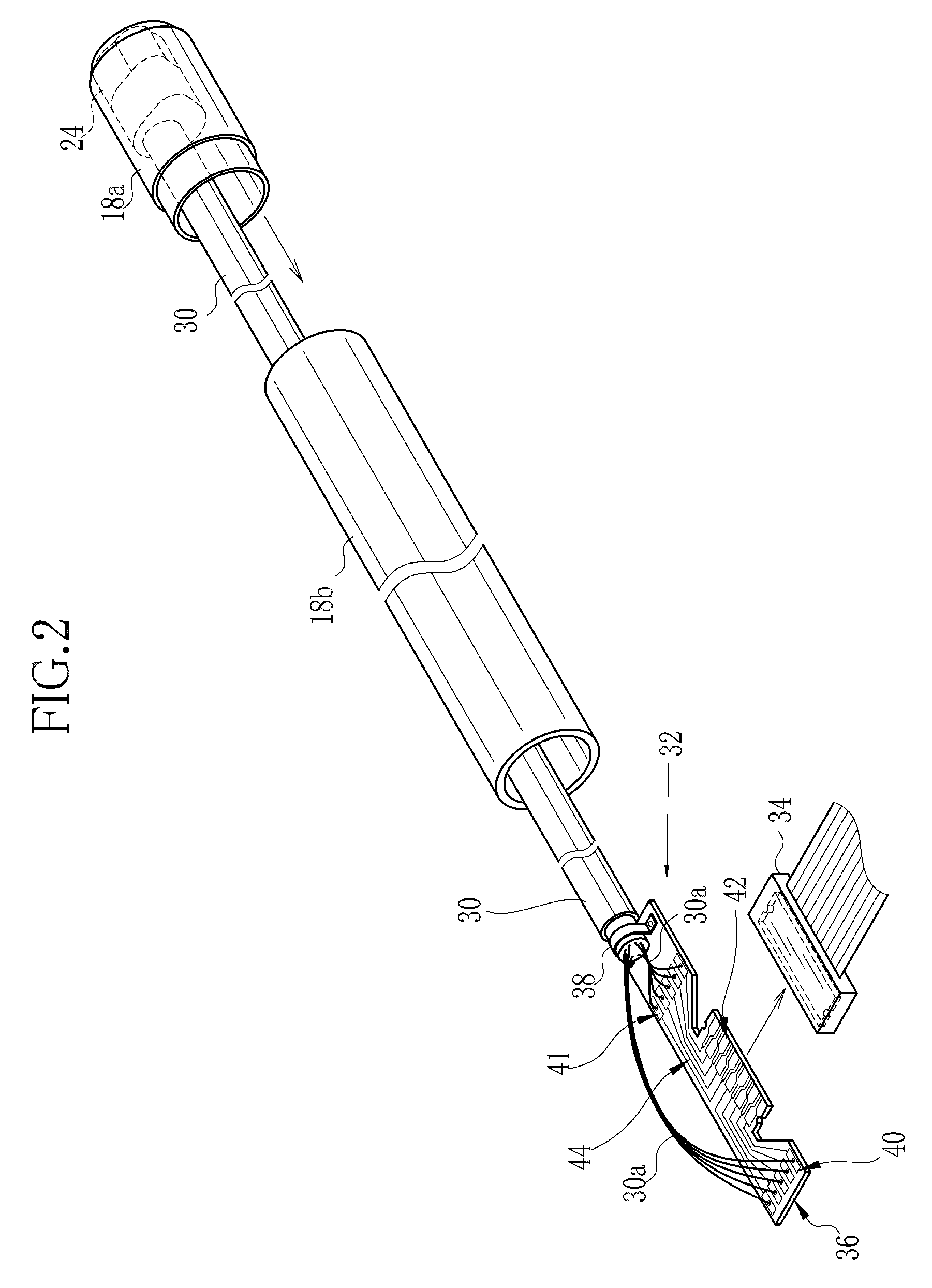
A cable connector includes a circuit board, having a predetermined width in a manner passable through an elongated tube of an endoscope apparatus, disposed to extend in an axial direction. A terminal group is formed on the circuit board, for electrically contacting a socket connector. First and second land patterns are formed on the circuit board, arranged in the axial direction so that the terminal group is disposed therebetween, wherein a front end of a first electric line group having lines among electric lines of a cable structure is electrically coupled to the first land pattern, and a front end of a second electric line group having lines among the electric lines is coupled to the second land pattern. A wiring pattern is formed on the circuit board, for electrically coupling the first land pattern to the terminal group and coupling the second land pattern to the terminal group.

Description

BACKGROUND OF THE INVENTION [0001]1. Field of the Invention[0002]The present invention relates to a cable connector and an endoscope apparatus. More particularly, the present invention relates to a cable connector and an endoscope apparatus, in which a high number of electric lines of a cable structure can be coupled for electrical connection in a simplified structure and safely without problems in transmitting operation.[0003]2. Description Related to the Prior Art[0004]An endoscope apparatus includes an elongated tube, a tip device and a circuit device or electrical device. The elongated tube is entered in a body cavity of a patient's body to be diagnosed. The tip device is disposed at a distal end of the elongated tube. The circuit device is contained in the tip device or disposed behind the tip device. Examples of the circuit device are a camera module, imaging unit or ultrasonic transducer. A cable structure is connected with the circuit device and extends in an axial direction...

Claims


Application Information

Patent Timeline
IPC IPC(8): H01R12/71A61B1/005A61B1/00
CPCA61B1/05H01R12/53A61B1/005H01R12/712A61B1/00124H01R12/721A61B1/009A61B1/00066A61B1/00114A61B1/051
Inventor SAKAMOTO, TOSHIO
Owner FUJIFILM CORP
Learn More