Bi-directional switch using series connected n-type mos devices in parallel with series connected p-type mos devices

a series connection, mos device technology, applied in electronic switching, semiconductor devices, pulse techniques, etc., can solve the problems of inability to realize inability to achieve parallel configuration of both types of series connection, and inability to form switches. the effect of high supply current and slow switching speed

Active Publication Date: 2013-09-26
ANALOG DEVICES INC
View PDF3 Cites 9 Cited by
  • Summary
  • Abstract
  • Description
  • Claims
  • Application Information

AI Technical Summary

Benefits of technology

[0005]In a second embodiment, the bi-directional switch is a DMOS switch including a pair of series connected NDMOS devices connected in parallel with a pair of series connected PDMOS devices. One advantage of the bi-directional DMOS switch in accordance with the second embodiment is that the switch allows rail-to-rail operation without the need to use a charge pump, e.g., a charge pump to generate the gate voltage for a conventional DMOS switch. To support rail-to-rail operation, the charge pump generates a supply voltage that exceeds the maximum allowed input signal in order to keep the conventional DMOS switch turned on. Disadvantages of using the charge pump in this manner include high supply current and slow switching speed. The DMOS switch of the present invention would avoid these disadvantages.

Problems solved by technology

However, no switches have been formed using a combination of series connected NDMOS and series connected PDMOS devices.
Therefore, a plurality of processes (e.g., a conventional NDMOS process plus a conventional PDMOS process) would be required in order to form a single switch having both types of series connections—which would be costly and time consuming.
Since both types of series connections would not have been used together, a parallel configuration of both types of series connections would also not have been considered feasible or practical.
Disadvantages of using the charge pump in this manner include high supply current and slow switching speed.

Method used


Image

  • Bi-directional switch using series connected n-type mos devices in parallel with series connected p-type mos devices
  • Bi-directional switch using series connected n-type mos devices in parallel with series connected p-type mos devices

Examples


Embodiment Construction

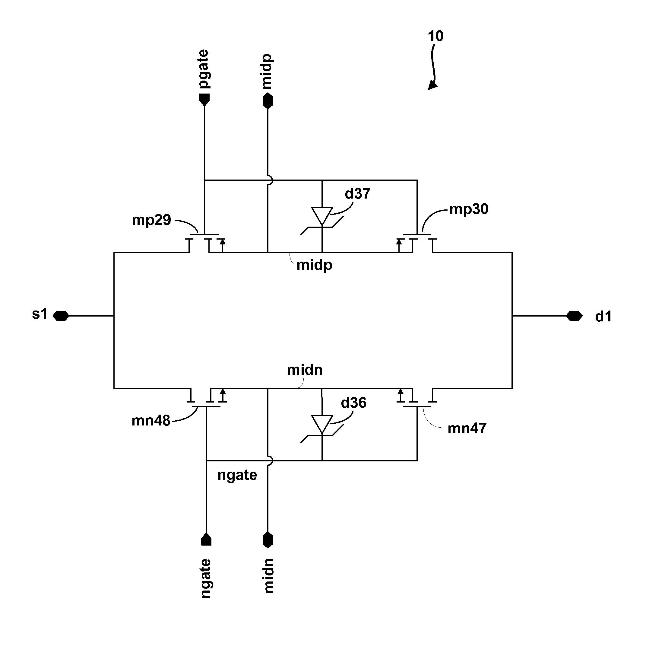
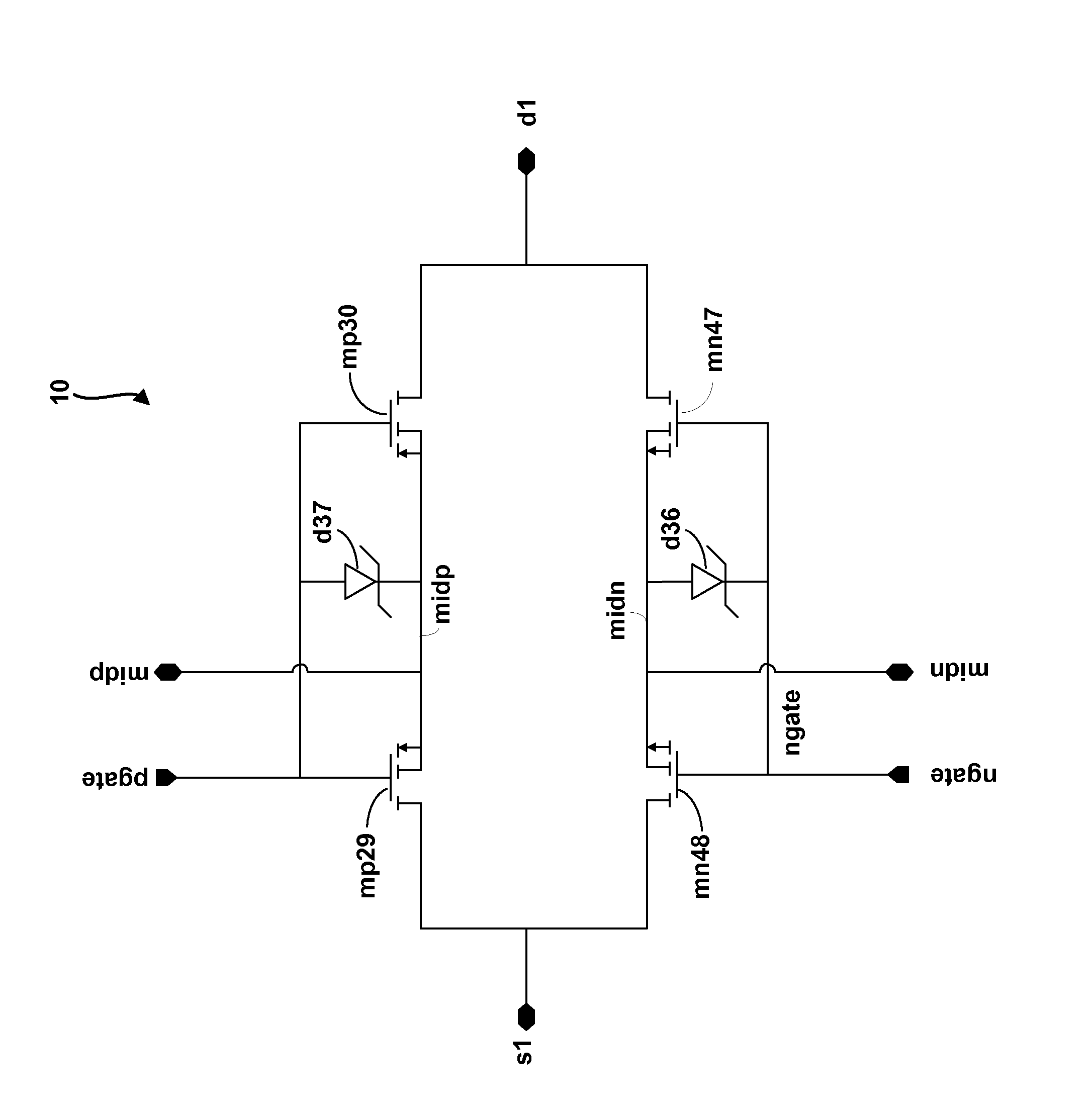
[0007]The present invention relates to a bi-directional switch that is formed using a pair of series connected N-type MOS devices connected in parallel with a pair of series connected P-type MOS devices. In one embodiment, the MOS devices are DMOS devices. The switch is capable of being operated as a rail-to-rail switch, meaning that the input to the switch can vary between the value of a positive supply rail (LHI) and the value of a negative supply rail (VSS) without adversely affecting switch operation. LHI and VSS are not shown in the drawings and represent the power supplies to a circuit that generates the input to the switch. For example, LHI and VSS may supply an amplifier circuit that boosts the voltage level of an input signal before the input is sent to the switch.

[0008]FIG. 1 shows a schematic of a DMOS switch 10 according to an example embodiment of the present invention. The switch 10 includes a pair of series connected PDMOS devices mp29 / mp30 and a pair of series connec...


PUM


Abstract

A bi-directional switch circuit includes a pair of N-type MOS devices connected in series with a common source terminal, and a pair of P-type MOS devices connected in series with a common source terminal. The series connected N-type devices are connected in parallel with the series connected P-type devices in a configuration that includes a first input/output (I/O) point of the switch circuit being connected to a drain of a first one of the N-type devices and a drain of a first one of the P-type devices. The parallel configuration also includes a second I/O point of the switch circuit being connected to a drain of a second one of the N-type devices and a drain of a second one of the P-type devices.

Description

CROSS-REFERENCE TO RELATED APPLICATIONS[0001]This application claims the benefit, under 35 U.S.C. §119(e), of U.S. Provisional Patent Application No. 61 / 613,269 and U.S. Provisional Patent Application No. 61 / 613,260, both filed on Mar. 20, 2012, the contents of which are hereby incorporated by reference in its entirety.BACKGROUND INFORMATION[0002]Two NDMOS devices can be connected in series with their sources connected to each other and their gates connected to each other to make an NDMOS switch. Two PDMOS devices can also be connected in series with their sources connected to each other and their gates connected to each other to make a PDMOS switch. However, no switches have been formed using a combination of series connected NDMOS and series connected PDMOS devices. The reason why these two types of series connections have not been combined into a single switch is that in a conventional DMOS manufacturing process one of the device types has to have its source tied to the silicon s...

Claims


Application Information

Patent Timeline
Patent Type & Authority Applications(United States)
IPC IPC(8): H01L29/747
CPCH03K2217/0054H03K17/6872
Inventor AHERNE, DAVIDDUNLEA, JOHN O.
Owner ANALOG DEVICES INC
Why Eureka
Try Eureka