Wireless power receiver and method of manufacturing the same
a technology of wireless power receiver and manufacturing method, which is applied in the direction of magnets, magnetic bodies, instruments, etc., can solve the problems of complex manufacturing process, short transmission distance of power, and thick thickness of wireless power receivers disposed in terminals, so as to achieve remarkable reduction of thickness reduce overall size of wireless power receivers.
- Summary
- Abstract
- Description
- Claims
- Application Information
AI Technical Summary
Benefits of technology
Problems solved by technology
Method used
Image

Examples
first embodiment
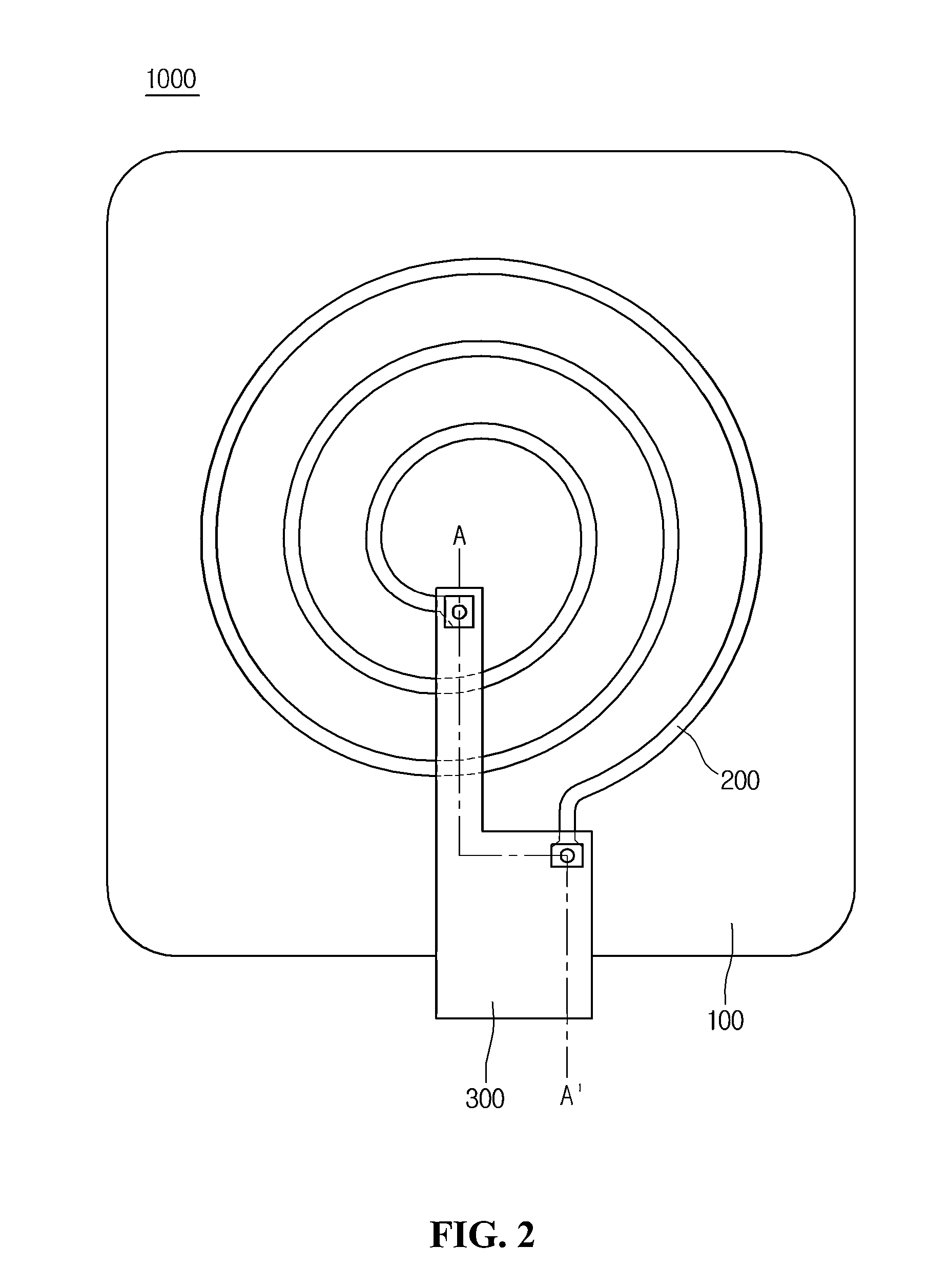
[0071]FIGS. 2 and 3 are views for explaining the structure of the wireless power receiver 1000 in detail when the coil unit 200 is connected with the connecting unit 300.
[0072]FIG. 2 is a plan view illustrating the wireless power receiver 1000 according to the first embodiment.
[0073]FIG. 2 shows the coil unit 200 connected with the connecting unit 300.
[0074]According to one embodiment, the connection between the coil unit 200 and the connecting unit 300 may be achieved by a solder. In detail, the first connection terminal 210 of the coil unit 200 may be connected to the first connection terminal 310 of the connecting unit 300 through a first solder 10 and the second connection terminal 220 of the coil unit 200 may be connected to the second connection terminal 320 of the connecting unit 300 through a second solder 20. In more detail, the first connection terminal 210 of the coil unit 200 may be connected to the first connection terminal 310 of the connecting unit 300 through a via ...
second embodiment
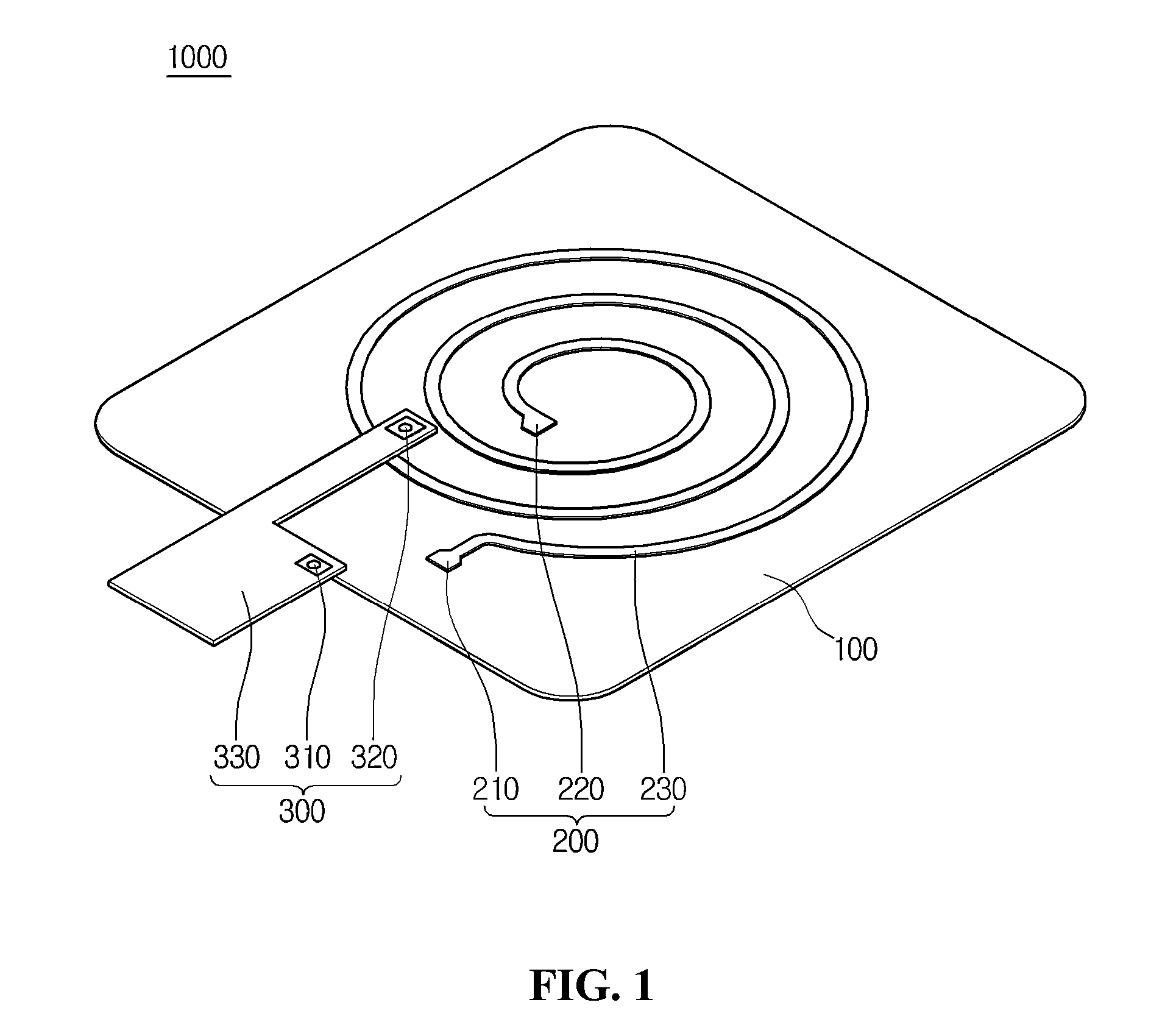
[0097]As described above, since the coil unit 200 is directly disposed on the top surface of the magnetic substrate 100, the overall thickness of the wireless power receiver 1000 can be remarkably reduced. In addition, since the wireless power receiver 1000 can be manufactured only through the laminating and etching processes, the manufacturing process may be simplified. FIG. 9 is a sectional view taken along line A-A′ of the connecting unit 300 of the wireless power receiver 1000 shown in FIG. 2 according to the
[0098]Referring to FIG. 9, the wireless power receiver 1000 may include a magnetic substrate 100, a coil unit 200, a connecting unit 300 and an adhesive layer 700.
[0099]The magnetic substrate 100, the coil unit 200, and the connecting unit 300 are identical to those described with reference to FIG. 1.
[0100]The adhesive layer 700 is interposed between the magnetic substrate 100 and the coil unit 200 to bond the magnetic substrate 100 to the coil unit 200.
third embodiment
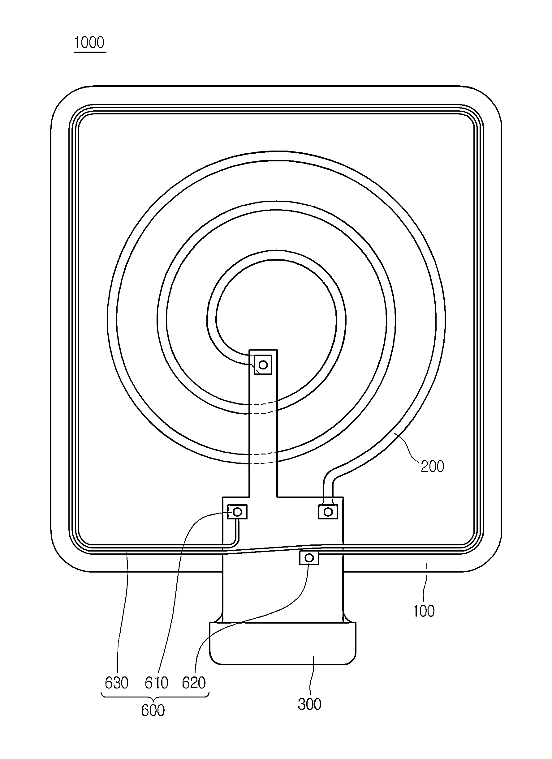
[0101]FIG. 10 is a plan view illustrating a wireless power receiver 1000 according to the
[0102]Referring to FIG. 10, the wireless power receiver 1000 may include a magnetic substrate 100, a coil unit 200, a connecting unit 300 and a short-range communication antenna 600.
[0103]The magnetic substrate 100, the coil unit 200 and the connecting unit 300 are identical to those described with reference to FIGS. 1 to 3.
[0104]The short-range communication antenna 600 includes a first connection terminal 610, a second connection terminal 620 and an outer peripheral coil 630.
[0105]The first connection terminal 610 and the second connection terminal 620 of the short-range communication antenna 600 are connected to the connecting unit 300.
[0106]The short-range communication antenna 600 can make near field communication with a reader. The short-range communication antenna 600 may serve as an antenna that transceives information in cooperation with the reader.
[0107]According to one embodiment, the...
PUM
| Property | Measurement | Unit |
|---|---|---|
| thickness | aaaaa | aaaaa |
| thickness | aaaaa | aaaaa |
| thickness | aaaaa | aaaaa |
Abstract
Description
Claims
Application Information
 - R&D
- Intellectual Property
- Life Sciences
- Materials
- Tech Scout
- Unparalleled Data Quality
- Higher Quality Content
- 60% Fewer Hallucinations
Browse by: Latest US Patents, China's latest patents, Technical Efficacy Thesaurus, Application Domain, Technology Topic, Popular Technical Reports.
© 2025 PatSnap. All rights reserved.Legal|Privacy policy|Modern Slavery Act Transparency Statement|Sitemap|About US| Contact US: help@patsnap.com