
Electric actuator

a technology of electric actuators and actuators, applied in the direction of fixed connections, contact members penetrating/cutting insulation/cable strands, coupling device connections, etc., can solve the problems of deteriorating electric connection between the first pressure contact element and the second pressure contact element, and the large retaining force of the fork-shaped tip end portion relative to the insertion web cannot be obtained, so as to prevent the occurrence of displacement of the first connecting terminal

Active Publication Date: 2013-09-26
HITACHI ASTEMO LTD
View PDF6 Cites 51 Cited by
  • Summary
  • Abstract
  • Description
  • Claims
  • Application Information

AI Technical Summary

Benefits of technology

The electric actuator described in this patent can create a stable connection between two components by using elastic contact flaps that bite into the tip end of a first connecting terminal, providing a rigid connection that helps maintain electrical connection. The actuator also has guide portions that can help guide the first connecting terminal smoothly into position. These features allow for a more reliable and efficient connection between two components, reducing the likelihood of connection failures.

Problems solved by technology

Unless the fork-shaped tip end portion is fully inserted into the insertion web to reach a predetermined insertion position, a large retaining force of the fork-shaped tip end portion relative to the insertion web cannot be obtained.
As a result, in a case where the fork-shaped tip end portion is not fully inserted, it is likely that an electric connection between the first pressure contact element and the second pressure contact element is deteriorated due to vibration or the like.

Method used


Image

  • Electric actuator
  • Electric actuator
  • Electric actuator

Examples


first embodiment

Operation of First Embodiment

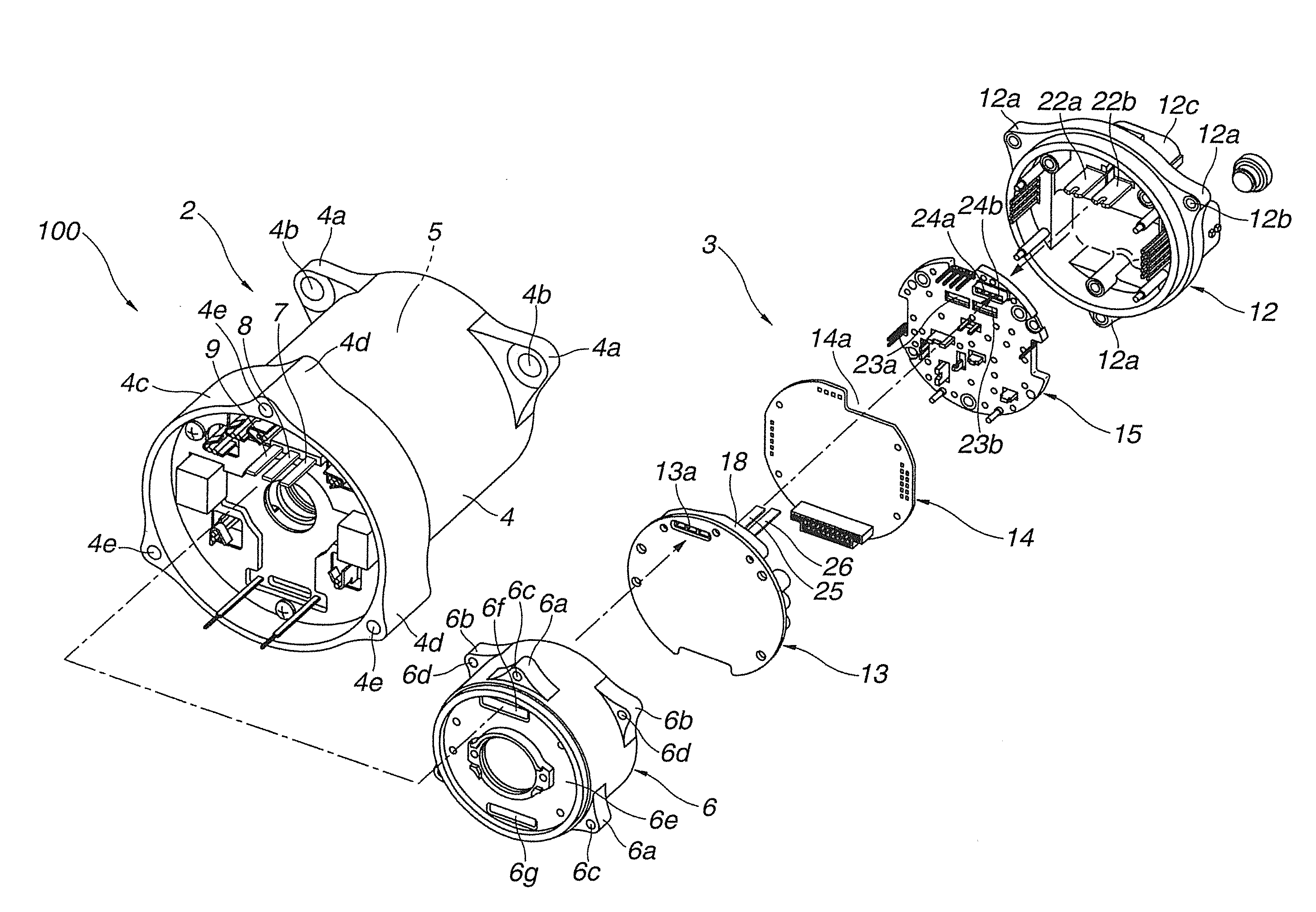
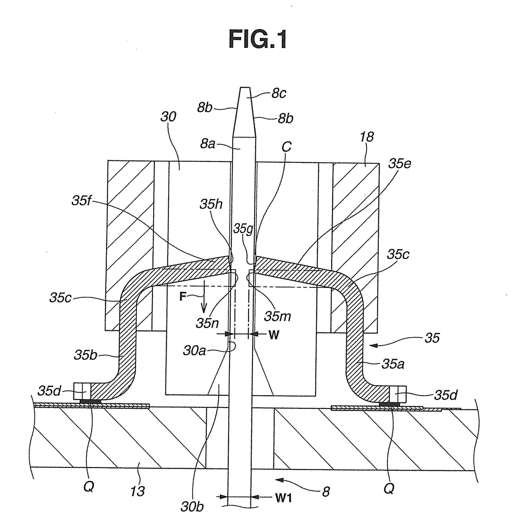
[0068]An operation of the electric actuator of the first embodiment will be explained hereinafter. Basically, an operation of connecting three-phase terminals 7-9 to corresponding female terminals 34-36 of terminal holder 18 is explained. An operation of connecting current-carrying terminals 25, 26 to corresponding female terminals 32, 33 is same as that of connecting three-phase terminals 7-9 to corresponding female terminals 34-36, and therefore, detailed explanations therefor are omitted.

[0069]Specifically, when motor housing 4, ECU housing 6, and cover 12 are assembled together, as shown in FIG. 5, firstly, the pair of current-carrying terminals 25, 26 are connected to terminal holder 18 by inserting base end portions 25a, 26a thereof into the respective clearances C between tip end portions 32e, 32f of split parts 32a, 32b of female terminal 32 and tip end portions 33e, 33f of split parts 33a, 33b of female terminal 33. In this state, three-phase te...

second embodiment

[0083]Referring to FIG. 9, an essential part of an electric actuator according to a second embodiment of the present invention is explained. The second embodiment differs from the first embodiment in provision of cutout grooves in opposed tip end portions 32e, 32f to 36e, 36f of split parts 32a, 32b to 36a, 36b of female terminals 32-36 and provision of an adhesive in the vicinity of the clearances C between opposed tip end portions 32e, 32f to 36e, 36f. As shown in FIG. 9, in electric actuator 200 of the second embodiment, semi-circular cutout grooves 32i, 32j to 36i, 36j are formed at both side edges of respective root portions of opposed tip end portions 32e, 32f to 36e, 36f, and exposed into each of through holes 27-31 of terminal holder 18. That is, the root portions are projected from the resin material of terminal holder 18 into respective through holes 27-31.

[0084]Adhesive 37 is applied to the vicinity of the respective clearances C between opposed tip end portions 32e, 32f ...


PUM

PropertyMeasurementUnit
Thicknessaaaaaaaaaa
Widthaaaaaaaaaa

Abstract

An electric actuator including a first electric circuit having a first connecting terminal, and a second electric circuit having a second connecting terminal electrically connected with the first connecting terminal, the first connecting terminal including a tip end portion having a rectangular flat plate shape, the second connecting terminal including a pair of elastic contact flaps opposed to each other with a clearance, the clearance having a width between tip end surfaces of the elastic contact flaps which is smaller than a thickness of the first connecting terminal. The first connecting terminal is retained such that the tip end portion thereof is clamped between the tip end surfaces of the elastic contact flaps of the second connecting terminal by an elastic restoring force of the elastic contact flaps.

Description

BACKGROUND OF THE INVENTION[0001]The present invention relates to an electric actuator, for example, an electric actuator useable in an electric power steering apparatus of a vehicle.[0002]As generally known, in an electric power steering apparatus of a vehicle, a rotational driving force of an electric motor as an electric actuator is used in order to assist a steering operation of a vehicle driver.[0003]The electric motor is controlled by a control unit including electronic equipments such as a relay circuit, a capacitor, etc. A plurality of electric circuits such as a power circuit and a control circuit, are connected to the control unit through connecting terminals.[0004]Japanese Patent Application Unexamined Publication No. 2010-508646 A discloses a connection apparatus including a first pressure contact element as a female terminal which has a strip-shaped resin-molded insertion web, and a second pressure contact element as a male terminal which has a flat plate shape having a...

Claims


Application Information

Patent Timeline
IPC IPC(8): H02K11/00H02K15/00
CPCB62D5/0406H02K11/0094H02K15/00Y10T29/49009H02K11/0073H01R12/58H01R13/112H02K5/225H02K11/33B62D5/04H01R4/24H01R13/631H02K5/22
Inventor MOTODA, HARUAKI
Owner HITACHI ASTEMO LTD
Features
  • Generate Ideas
  • Intellectual Property
  • Life Sciences
  • Materials
  • Tech Scout
  • Unparalleled Data Quality
  • Higher Quality Content
  • 60% Fewer Hallucinations
Learn More