Method and control device to operate a magnetic resonance system

a magnetic resonance and control device technology, applied in the field of method to operate a magnetic resonance tomography system, can solve the problems of wide-ranging compromises in resolution, contrast and tendency to artifacts, examination costs,

Active Publication Date: 2013-09-26
SIEMENS HEALTHCARE GMBH
View PDF5 Cites 47 Cited by
  • Summary
  • Abstract
  • Description
  • Claims
  • Application Information

AI Technical Summary

Benefits of technology

[0021]A TSE pulse sequence with which m different slices can be excited, and the signal emitted by these m slices can subsequently be simultaneously refocused with a series of refocusing pulses, is thus provided by the invention, wherein the echo signals of the m slices that are created after each of these refocusing pulses can be acquired in temporally separate readout windows. By the simultaneous refocusing, the radio-frequency energy that is accumulated via the refocusing pulses is thereby reduced by approximately a factor of m relative to the separate acquisition of the m slices (with corresponding refocusing pulses and flip angles). It is thus possible to reduce the examination duration of a SAR-limited measurement at a given resolution by approximately a factor of m relative to the prior art. Alternatively, a higher resolution can be achieved in a given examination duration.
[0045]In a second variant, a complex-value combination of image data of a specific slice whose raw data were acquired in various readout windows with a single echo train takes place in a second variant. This complex-value combination advantageously takes place after the phase—which spatially varies slowly in image space—was removed via computation. Alternatively, instead of the computer elimination of the phase that spatially varies slowly in image space a different method can also be used that avoids the destructive interference of the signals from different readout windows.

Problems solved by technology

One of the major challenges in the future development in magnetic resonance imaging is an acceleration of magnetic resonance sequence techniques without wide-ranging compromises with regard to resolution, contrast and tendency towards artifacts.
In addition, the examination duration of an MR examination is directly linked with the patient throughput, and therefore the examination costs.
A TSE sequence technique, however, is a relatively slow sequence technique in comparison to EPI techniques and is characterized by high radio-frequency radiation into the patients due to the large number of refocusing pulses.
Due to the cited SAR problem, however, such a new TSE sequence technique with a simultaneous acquisition of multiple slices will then only be able to shorten the actual examination duration when the radio-frequency radiation at least does not increase per time period.
An additional difficulty in the design of such novel TSE sequences is the fact that the refocusing pulses are normally not perfect 180° pulses.
An inherent, unavoidable reason for this is that the slice profile is not exactly rectangular (due to the finite duration of the RF pulses), and thus deviates from the ideal 180° at least at the slice edges.
If these spins accumulate along the different coherent echo paths of different phase portions, this leads to destructive interference.
The signal collapses; the images calculated from the raw data show shadows and a poor signal-to-noise ratio (SNR); and the pulse sequence is not able to maintain a long echo train.
The simultaneous refocusing of the m slices causes the radiated radio-frequency energy to be reduced by approximately a factor of m. However, due to the spoiling of specific, coherent echo paths, the signal linked with these echo paths cannot be used for imaging, which leads to an SNR loss relative to the separate acquisition of the slices.
In addition, in this pulse sequence it is unfortunately not possible to maintain a long echo time (for example with more than 20 echoes).
Therefore, the pulse sequence cannot be used for T2-weighted imaging.

Method used


Image

  • Method and control device to operate a magnetic resonance system
  • Method and control device to operate a magnetic resonance system
  • Method and control device to operate a magnetic resonance system

Examples


Embodiment Construction

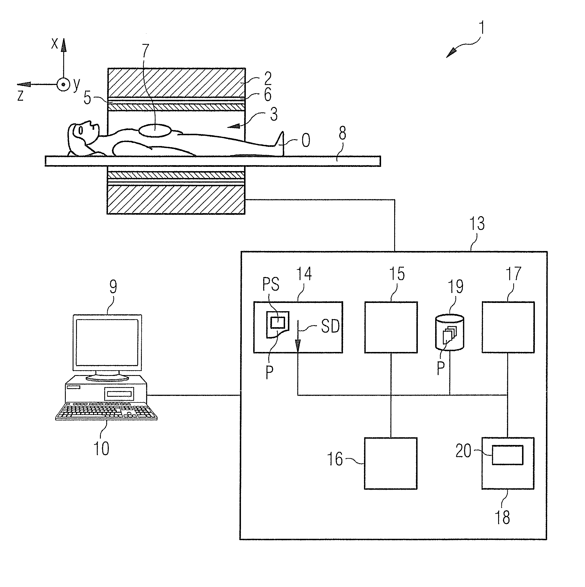
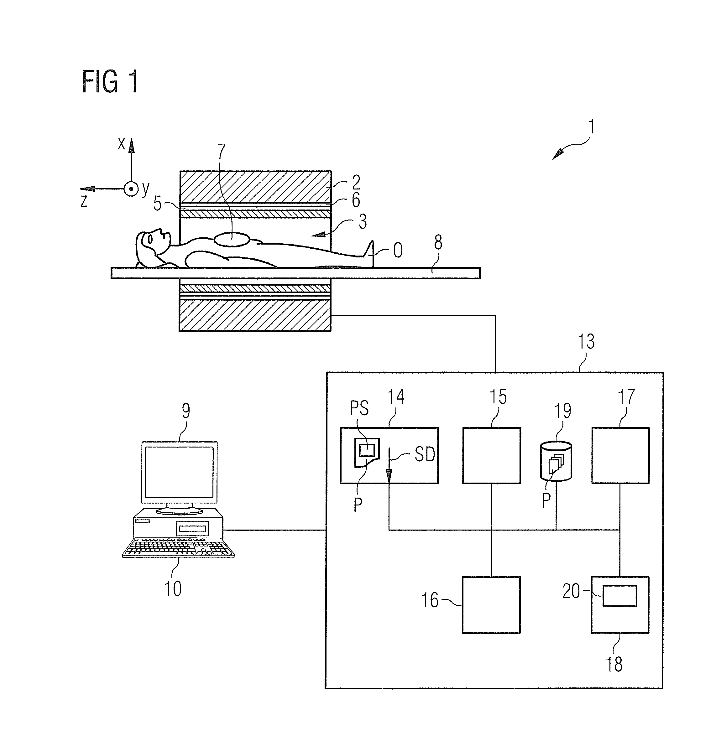
[0058]A magnetic resonance tomography system 1 (also shortened to “MR system” in the following) according to the invention is schematically presented in FIG. 1. They system includes the actual magnetic resonance scanner 2 with an examination space 3 or patient tunnel into which an examination subject O on a bed 8 can be moved. Here, the subject O is a patient or test subject in whose body the examination subject—a specific organ, for example—is located) on a bed 8 can be driven.

[0059]The magnetic resonance scanner 2 is typically equipped with a basic field magnet system 4, a gradient system 6 and an RF transmission antenna system 5 and an RF reception antenna system 7. In the shown exemplary embodiment, the RF transmission antenna system 5 is a whole-body coil permanently installed in the magnetic resonance scanner 2, in contrast to which the RF reception antenna system 7 includes local coils (symbolized by only a single local coil in FIG. 1) to be arranged on the patient or test su...


PUM


Abstract

In a method and a control device for operation of a magnetic resonance tomography system to generate image data, multiple of slices in an examination subject are initially excited at a first time interval by a respective RF slice excitation pulse of a series of spatially selective slice excitation pulses. An RF refocusing pulse is then emitted at a second time interval after the first excitation pulse or after the last excitation pulse of the series of RF slice excitation pulses. At least one additional RF refocusing pulse is emitted at a third time interval after a preceding RF refocusing pulse. The third time interval is twice as long as the second time interval. The width of the RF refocusing pulses is selected to generate a number of chronologically separate echo signals per RF refocusing pulse for simultaneous refocusing of all excited slices.

Description

BACKGROUND OF THE INVENTION[0001]1. Field of the Invention[0002]The invention concerns a method to operate a magnetic resonance tomography system (MT system) to generate magnetic resonance image data of an examination subject, of the type wherein a number of slices in the examination subject are excited within a sequence module by respective RF slice excitation pulses of a series of a spatially selective RF slice excitation pulses, and then multiple RF refocusing pulses are emitted, and wherein the width of the RF refocusing pulses for generation of a number of time-separated echo signals is selected per RF refocusing pulse such that it encompasses at least a portion of an excitation volume of all excited slices for simultaneous refocusing of all excited slices. Furthermore, the invention concerns a method to generate magnetic resonance image data of an examination subject, wherein raw data are used that were acquired by a magnetic resonance tomography system using such a method. Mo...

Claims


Application Information

Patent Timeline
Patent Type & Authority Applications(United States)
IPC IPC(8): G01R33/54G01R33/44
CPCA61B5/055G01R33/4824G01R33/543G01R33/44G01R33/4835
Inventor STEMMER, ALTO
Owner SIEMENS HEALTHCARE GMBH
Why Eureka
Try Eureka