Determination of a magnetic resonance system control sequence

a magnetic resonance system and control sequence technology, applied in the direction of magnetic variable regulation, measurement using nmr, instruments, etc., can solve the problems of increased risk, higher risk of artifact formation in images, and one-dimensional, two-dimensional or multi-dimensional k-space trajectories for selective excitation with a higher complexity compared to the typically used trajectories, etc., to achieve fast and optimally robust calculations of optimized k-space trajectories

Active Publication Date: 2013-09-26
SIEMENS HEATHCARE GMBH
View PDF4 Cites 19 Cited by
  • Summary
  • Abstract
  • Description
  • Claims
  • Application Information

AI Technical Summary

Benefits of technology

[0012]An object of the present invention is to provide an improved method to determine a magnetic resonance system control sequence and a corresp

Problems solved by technology

Such one-dimensional, two-dimensional or multidimensional k-space trajectories for a selective excitation have a higher complexity in relation to the typically used trajectories with constant gradients that are used for a simple, slice-selective excitation.
Due to this higher complexity, a higher risk of artifact formation in the images also exists, for example because such pulses can already be significantly longer.
Furthermore, an increased risk exists that hardware radio-frequency limitations and/or limitations with regard to the radio-frequency exposure of the patients (for example li

Method used


Image

  • Determination of a magnetic resonance system control sequence
  • Determination of a magnetic resonance system control sequence
  • Determination of a magnetic resonance system control sequence

Examples


Embodiment Construction

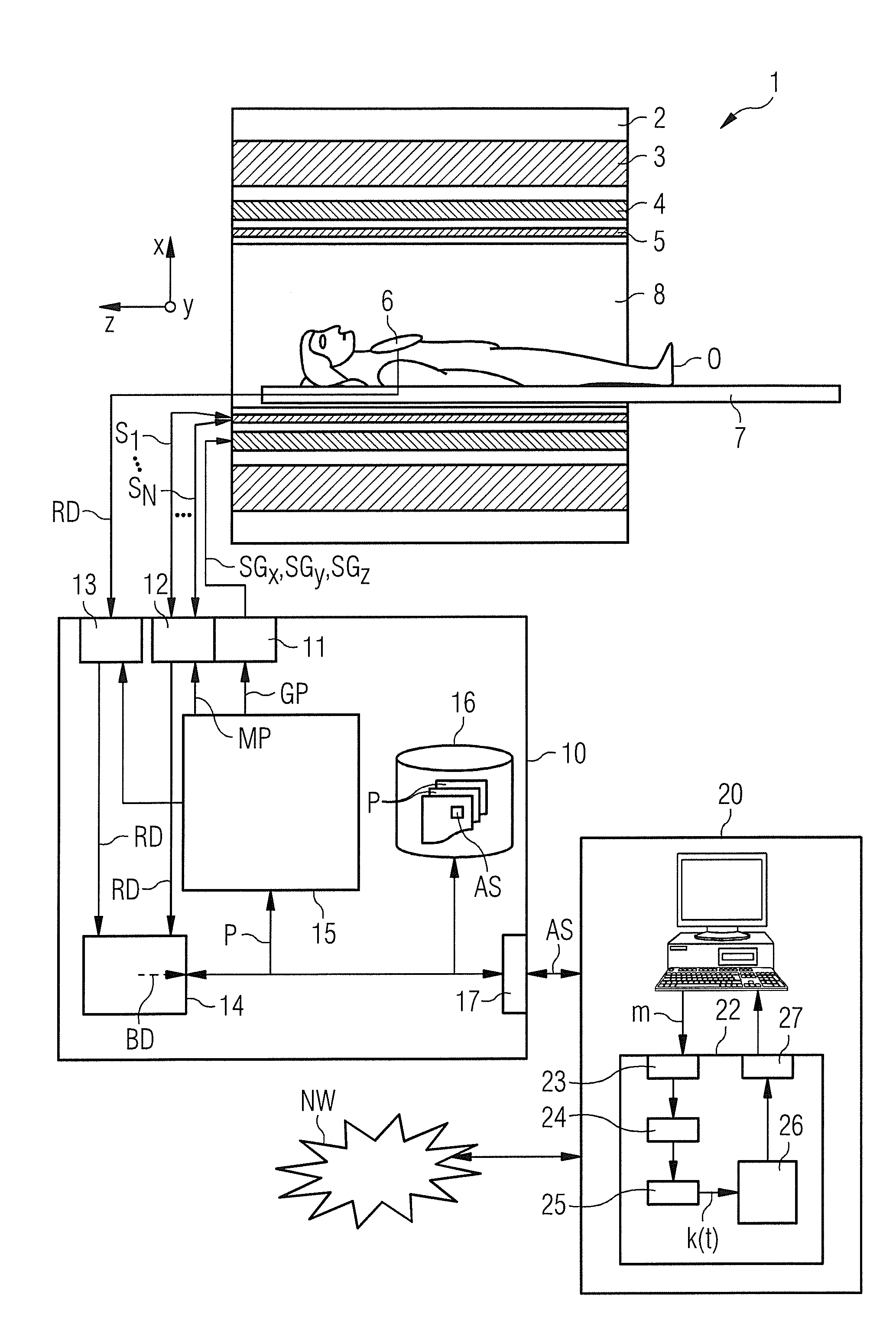
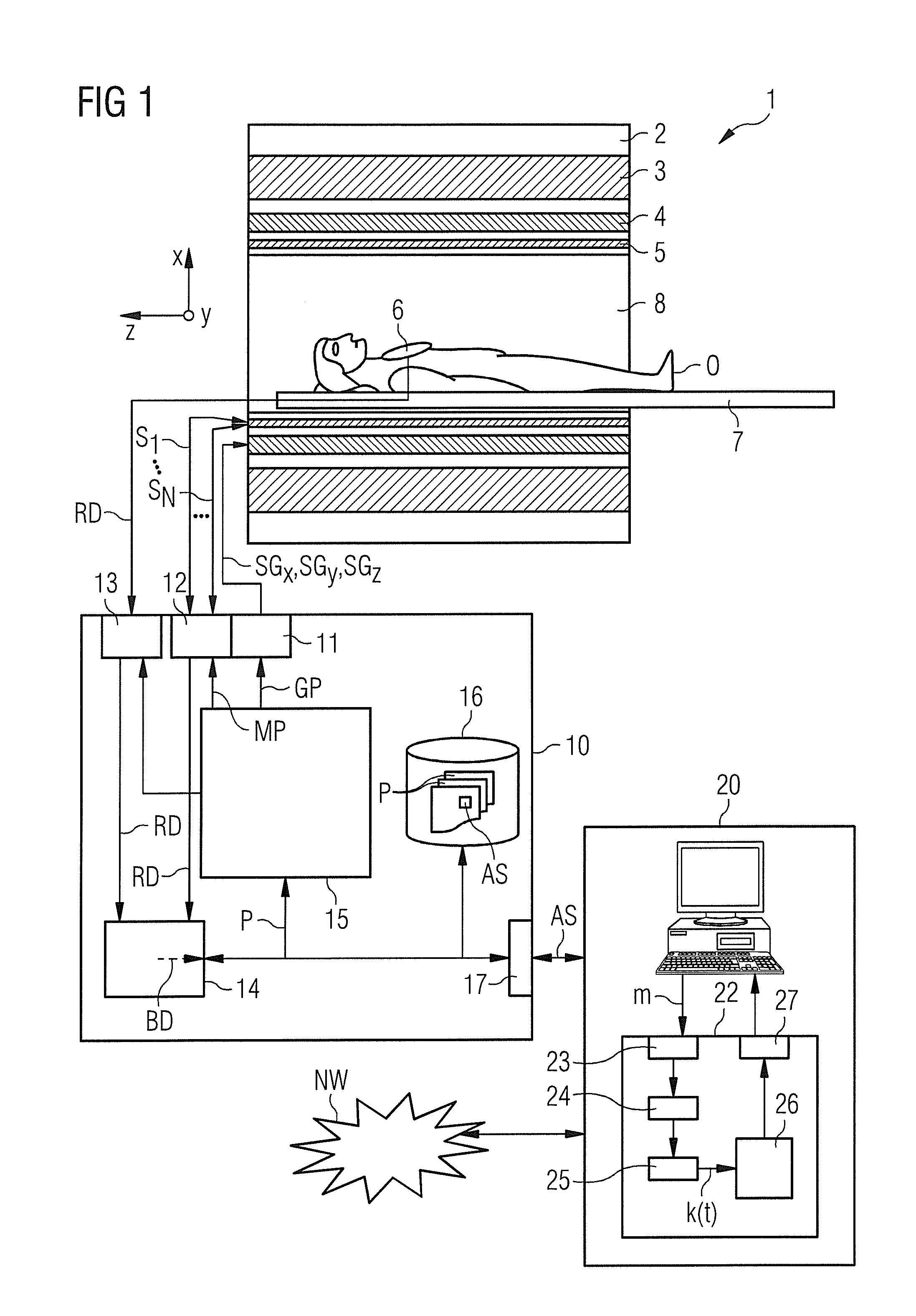
[0073]A magnetic resonance system 1 according to the invention is shown schematically in FIG. 1. The system 1 includes the actual magnetic resonance scanner 2 with an examination space 8 or patient tunnel that is located in the magnetic resonance scanner 2. A bed 7 can be driven into this patient tunnel 8, such that an examination subject O (patient / test subject) situated thereupon during an examination can be supported at a specific position within the magnetic resonance scanner 2 relative to the magnet system and radio-frequency system arranged therein, or can also be driven between different positions during a measurement.

[0074]Significant components of the magnetic resonance scanner 2 are a basic field magnet 3; a gradient system 4 with magnetic field gradient coils in order to apply arbitrary magnetic field gradients in the x-, y- and z-directions, and a whole-body radio-frequency coil 5. The receipt of magnetic resonance signals induced in the examination subject O can take pl...


PUM


Abstract

In method and a control sequence determination device to determine a magnetic resonance system control sequence that includes at least one radio-frequency pulse train to be emitted by a magnetic resonance system, a target magnetization (m) is initially detected, and an energy distribution function in k-space is determined on the basis of the target magnetization. A k-space trajectory is then determined under consideration of the energy distribution function in k-space, for which the radio-frequency pulse train is then determined in an RF pulse optimization method. The method is suitable for operation of a magnetic resonance system, and a magnetic resonance system includes such a control sequence determination device.

Description

BACKGROUND OF THE INVENTION[0001]1. Field of the Invention[0002]The invention concerns a method and a control sequence determination device to determine a magnetic resonance system control sequence. Moreover, the invention concerns a method to operate a magnetic resonance system using such a magnetic resonance system control sequence; as well as a magnetic resonance system with a radio-frequency transmission device, with a gradient system and a control device that is designed in order to emit a radio-frequency pulse train to implement a desired measurement on the basis of a predetermined control sequence, and to emit a gradient pulse train in coordination therewith via the gradient system.[0003]2. Description of the Prior Art[0004]In a magnetic resonance tomography system (shortened to “magnetic resonance system”), the body to be examined is typically exposed to a relatively high basic magnetic field (known as the B0 field)—for example of 3 or 7 Tesla—produced by a basic field magne...

Claims


Application Information

Patent Timeline
IPC IPC(8): G01R33/54G01R33/28
CPCG01R33/4833G01R33/4836G01R33/28G01R33/543G01R33/5612
Inventor PFEUFFER, JOSEFSCHNEIDER, RAINER
Owner SIEMENS HEATHCARE GMBH
Why Eureka
Try Eureka