Image recording device and image recording method

a recording device and image technology, applied in the field of image recording devices and image recording methods, can solve the problems of insufficient surface modification processing, waste of recording media, and risk of image inconsistency between the insufficient area and the other areas, and achieve the effect of increasing the adhesive properties of the liquid ejecting

Inactive Publication Date: 2013-09-26
SEIKO EPSON CORP
View PDF2 Cites 10 Cited by
  • Summary
  • Abstract
  • Description
  • Claims
  • Application Information

AI Technical Summary

Benefits of technology

[0006]However, with the aforementioned device that ejects a liquid such as ink on a recording medium to record an image, having the liquid be securely adhered to the recording medium is important. In light of that, it is conceivable to use a surface modifying apparatus such as a corona treater to execute surface modification processing on the recording medium. In specific terms, it is sufficient to arrange the surface modifying apparatus at the upstream side of the recording head in the recording medium conveyance path, and to execute surface modification processing on the recording medium that passes in front of the surface modifying apparatus as the recording medium is being conveyed. By doing this, the recording medium which has undergone surface modification processing is supplied to the recording head, and it is possible to increase the adhesive properties of the liquid ejected by the recording head onto the recording medium.

Problems solved by technology

When this kind of time difference is large, the recording medium passes in front of the surface modifying apparatus as is without surface modification processing being implemented, and there is the risk of a very long area with insufficient surface modification processing being generated on the recording medium.
In such a case, if an image is recorded leaving out the area for which surface modification processing is insufficient, the recording medium is consumed wastefully by the amount of this insufficient area, and if an image is recorded on the area for which surface modification processing is insufficient, there is the risk of image inconsistency occurring between the insufficient area and the other areas.
At that time, when the passage time starts (specifically, when the recording medium starts passing through the processing position at the passage velocity), if it is not possible for the surface modifying apparatus to start surface modification processing immediately, there was the risk that a large volume of the area for which surface modification processing is insufficient like that described above would be generated.
As a result, it is possible to keep the area for which the surface modification processing is insufficient small.

Method used


Image

  • Image recording device and image recording method
  • Image recording device and image recording method
  • Image recording device and image recording method

Examples


first embodiment

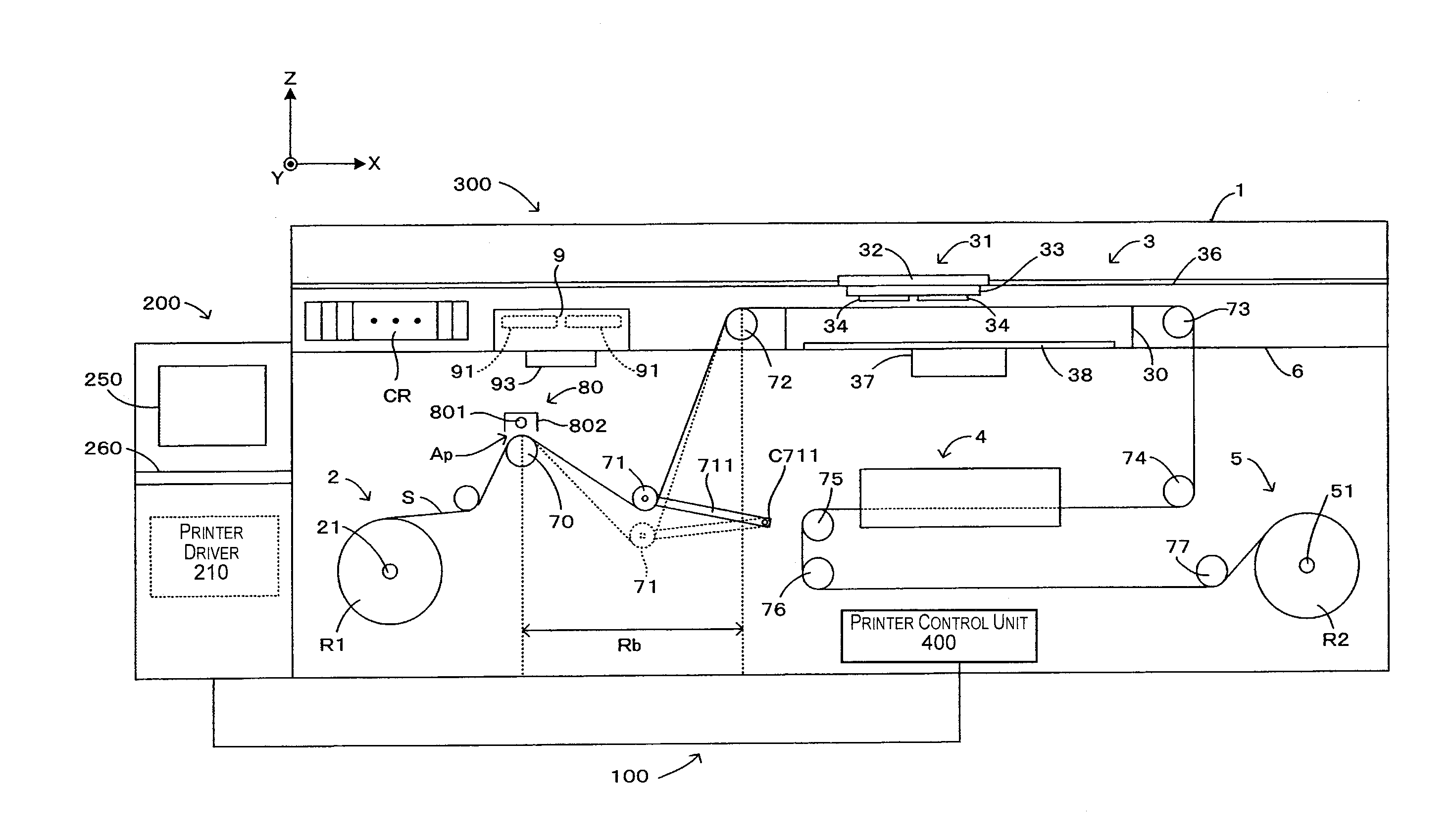
[0027]FIG. 1 is a pattern diagram showing an example of a printing system to which the present invention can be applied. Note that in FIG. 1 and the drawings thereafter, when necessary to clarify the arrangement relationship of each unit of the device, the X, Y, and Z orthogonal coordinates having the Z axis as the perpendicular axis are noted together. With the description below, the direction in which each coordinate axis (arrow) faces is the positive direction, and the opposite facing direction is the negative direction, and the Z axis positive side is handled as appropriate as the upper side, and the Z axis negative side as the lower side.

[0028]The printing system 100 is equipped with a host device 200 for generating printing data based on image data received from an external device such as a personal computer or the like, and a printer 300 for printing images based on the printing data received from the host device 200. This printer 300 prints an image (forms an image) using th...

second embodiment

[0073]FIG. 5 is a timing chart showing an example of the printing operation executed with the second embodiment. The difference between the second embodiment and the first embodiment is the timing at which the discharge instructions are output, so hereafter, we will give a description with this difference part as the focus, and for other parts, the correlating code numbers will be given, and descriptions will be omitted as appropriate. It goes without saying that by being equipped with constitutions in common with the first embodiment, that the same effects as those of the first embodiment are also exhibited with the second embodiment.

[0074]With the second embodiment, the mechanism controller 420 continuously outputs discharge instructions to the discharge bias generator 84 from the point in time when the passage time Tp starts through the point in time when a prescribed time Te has elapsed from when that passage time Tp ends. In other words, the discharge instructions output simult...

third embodiment

[0077]FIG. 6 is a timing chart showing an example of the printing operation executed with the third embodiment. The difference between the third embodiment and the aforementioned embodiments is the timing at which the sheet S passes through the processing position Ap and the timing at which discharge instructions are output, so hereafter, we will give a description with this difference part as the focus, and for other parts, the correlating code numbers will be given, and descriptions will be omitted as appropriate. It goes without saying that by being equipped with constitutions in common with the aforementioned embodiments, the same effects as those of the aforementioned embodiments are also exhibited with the third embodiment.

[0078]With the third embodiment, the outlet shaft 21 does not start conveying the sheet S until the prescribed time Te (>d) has elapsed from the point in time when conveying of the sheet S to the platen 30 by the roller 72 has started (in other words, the po...


PUM


Abstract

An image recording device includes a support member, a recording head, a surface modifying apparatus, a conveyor unit, and a control unit. The surface modifying apparatus executes surface modification processing to modify a surface of the recording medium at a processing position disposed on an upstream side of the support member. The conveyor unit intermittently passes the recording medium through the processing position at a prescribed passage velocity by feeding the recording medium from the upstream side of the conveyance path to the processing position. The control unit is capable of providing a processing execution signal to the surface modifying apparatus, and provides the processing execution signal to the surface modifying apparatus for a prescribed time within a wait time from when passage of the recording medium through the processing position stops until the recording medium starts passing through the processing position at the prescribed passage velocity.

Description

CROSS-REFERENCE TO RELATED APPLICATIONS[0001]This application claims priority to Japanese Patent Application No. 2012-063778 filed on Mar. 21, 2012. The entire disclosure of Japanese Patent Application No. 2012-063778 is hereby incorporated herein by reference.BACKGROUND[0002]1. Technical Field[0003]The present invention relates to technology for recording images by, while intermittently conveying a recording medium, ejecting a liquid on the recording medium when stopped, and specifically relates to technology for executing surface modification processing on a recording medium prior to the liquid being ejected on the recording medium.[0004]2. Related Art[0005]In Japanese Laid-Open Patent Application Publication No. 2011-194797 is noted an image recording device with which a recording head ejects ink on a recording medium supported on a platen to print an image on the recording medium. Specifically with this image recording device, the recording medium is intermittently conveyed over...

Claims


Application Information

Patent Timeline
Patent Type & Authority Applications(United States)
IPC IPC(8): B41J13/00
CPCB41J13/0009B41J11/42B41J11/0015
Inventor KATAGAMI, SATORUTOYA, AKIHIROSANTO, HIROYUKINAGASAWA, HIDEYUKI
Owner SEIKO EPSON CORP
Why Eureka
Try Eureka