Resin moldings

a technology of resin molded components and resin layered products, which is applied in the direction of synthetic resin layered products, thermoplastic polymer dielectrics, solid-state devices, etc., can solve the problems of still more difficult to obtain the metal than by wet methods such as electrolysis or electroless plating, and it is difficult to obtain a high effect of improving the adhesion between the resin molded component surface, so as to improve the adhesion between the metal

Inactive Publication Date: 2005-07-12
MATSUSHITA ELECTRIC WORKS LTD
View PDF21 Cites 9 Cited by
  • Summary
  • Abstract
  • Description
  • Claims
  • Application Information

AI Technical Summary

Benefits of technology

[0086]The resin molded component according to the third embodiment can improve the adhesion between the metal and the resin molded component surface more greatly without increasing the linear expansion coefficient of the formed resin molded component, in addition to the effects of the invention of the second embodiment, since a mixing amount of the rubber-like elastic material is between 0.5 and 10 parts in mass with respect to 100 parts in mass of the base resin.
[0087]The resin molded component according to the fourth embodiment provides excellent adhesion of the original metal layer and improved adhesion effects of the metal layer by the rubber-like elastic material, and further provides excellent heat resistance, mechanical properties, and chemical resistance, in addition to the effects of the invention of the first embodiment, since polyphthalamide or polyphenylene sulfide is used as the base resin.
[0088]The resin molded component according to the fifth embodiment can improve, in addition to the effects of the invention of the first embodiment, the dimensional stability of the resin molded component and suppress the generation of thermal deformation and the like, while securing the adhesion since the resin composition with an inorganic filler mixed is used as a resin composition.
[0089]The resin molded component according to the sixth embodiment, in addition to the effects of the invention of the fifth embodiment, depending on the inorganic filler being fibrous of 0.5 to 5 μm in diameter and 10 to 50 μm in length, can reduce the generation of molding warpage and thermal deformation since the anisotropy of physical properties caused by orientation by the flow of resin at the time of forming is relaxed and the difference of linear expansion coefficient and the molding shrinkage ratio between in the flow direction of resin composition and in the transverse direction is reduced, and the flatness at the time of molding (initial flatness) is excellent and thus, the change in flatness by heating can be reduced. Furthermore, it is possible to prevent the circuit conductive reliability from lowering by the circuit adhesion lowered as the resin molded component is thermally deformed.
[0090]The resin molded component according to the seventh embodiment can reduce the inorganic filler content depending on the inorganic filler being plate-form, in addition to the effects of the invention of the fifth embodiment, and can relax the anisotropy of physical properties caused by orientation by the flow of resin at the time of forming and the difference of the linear expansion coefficient and the molding shrinkage ratio between in the flow direction of resin composition and in the transverse direction to it further decreases and thus, the linear expansion coefficient also decreases. Since the generation of molding warpage and the thermal deformation can be reduced, the excellent flatness at the time of forming (initial flatness) is secured and at the same time, the change in flatness by heating can be reduced and the thermal deformation amount in-plane direction also can be reduced. Furthermore, it is possible to prevent the circuit conductive reliability from lowering by the circuit adhesion lowered as the resin molded component is thermally deformed.
[0091]The resin molded component according to the eighth embodiment can, in addition to the effects of the invention of the fifth embodiment, relax the anisotropy of physical properties caused by orientation in the flow direction of resin composition, in the transverse direction, and in the direction perpendicular to it (thickness direction) by the flow of resin at the time of forming, excellent initial flatness is achieved, since an inorganic fibrous filler of 0.5 to 5 μm in diameter and 10 to 50 μm in length and the plate-form inorganic filler are used together, and thus, the molding shrinkage ratio and the linear expansion coefficient can be kept small and the anisotropy can be suppressed to a small level irrespective of the flow direction of the resin composition, and consequently, it is not only possible to achieve excellent flatness at the time of molding (initial flatness) in all the surfaces and to reduce the change in the flatness being heating, but also possible to reduce the thermal deformation rate in the in-plane direction. Furthermore, it is possible to prevent the circuit conductive reliability from lowering by the circuit adhesion lowered as the resin molded component is thermally deformed.

Problems solved by technology

In particular, when the metal layer is formed on the surface of the resin molded component by the physical deposition method which is a dry method such as sputtering, vacuum evaporation, and ion plating, it is still more difficult to obtain the adhesion between the resin molded component and the metal than by wet method such as electrolysis or electroless plating.
However, in the present situation it is still difficult to obtain a high effect of improving the adhesion between the resin molded component surface and the metal layer only by activating the surface by plasma treatment.

Method used


Image

  • Resin moldings
  • Resin moldings
  • Resin moldings

Examples


example 1

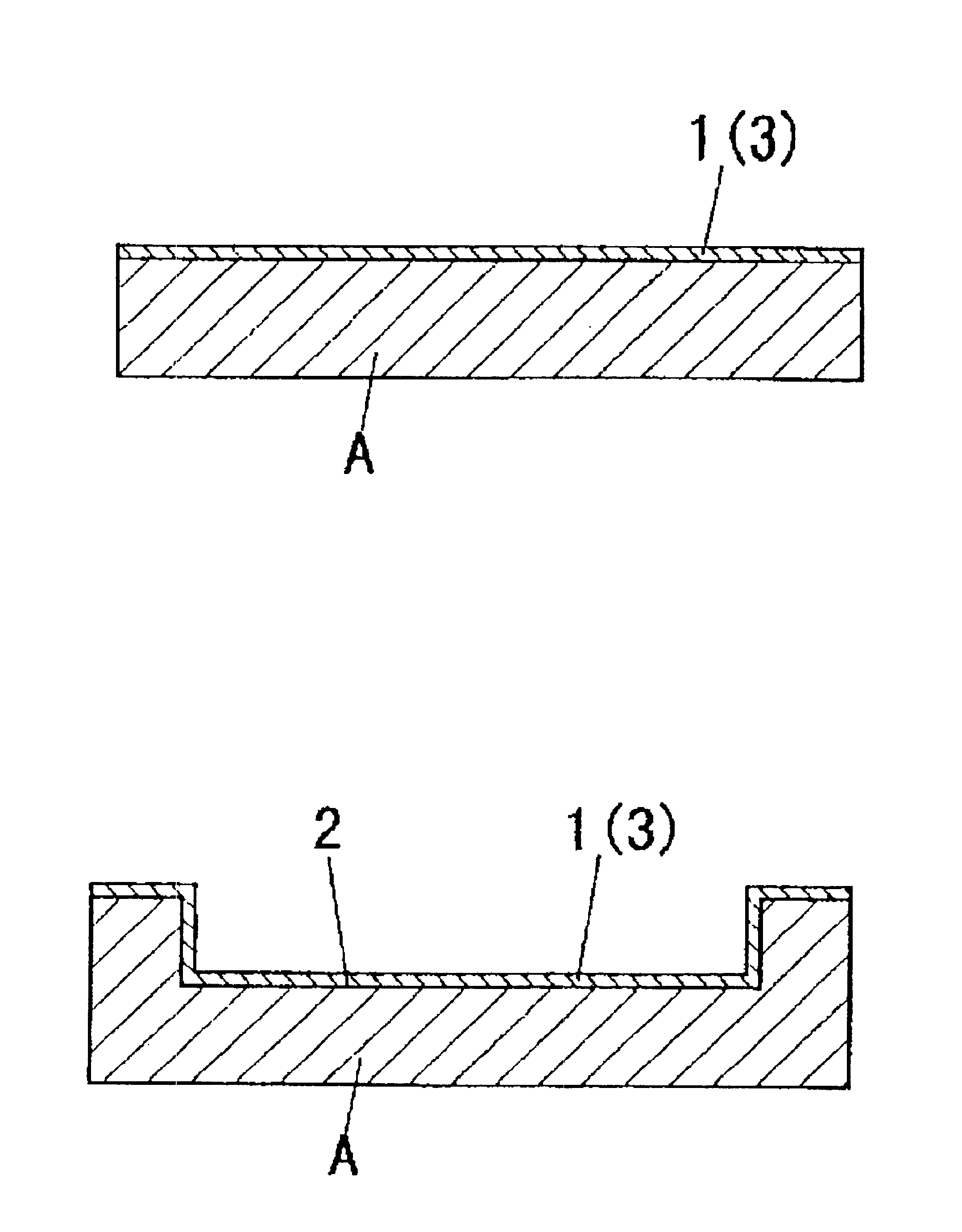
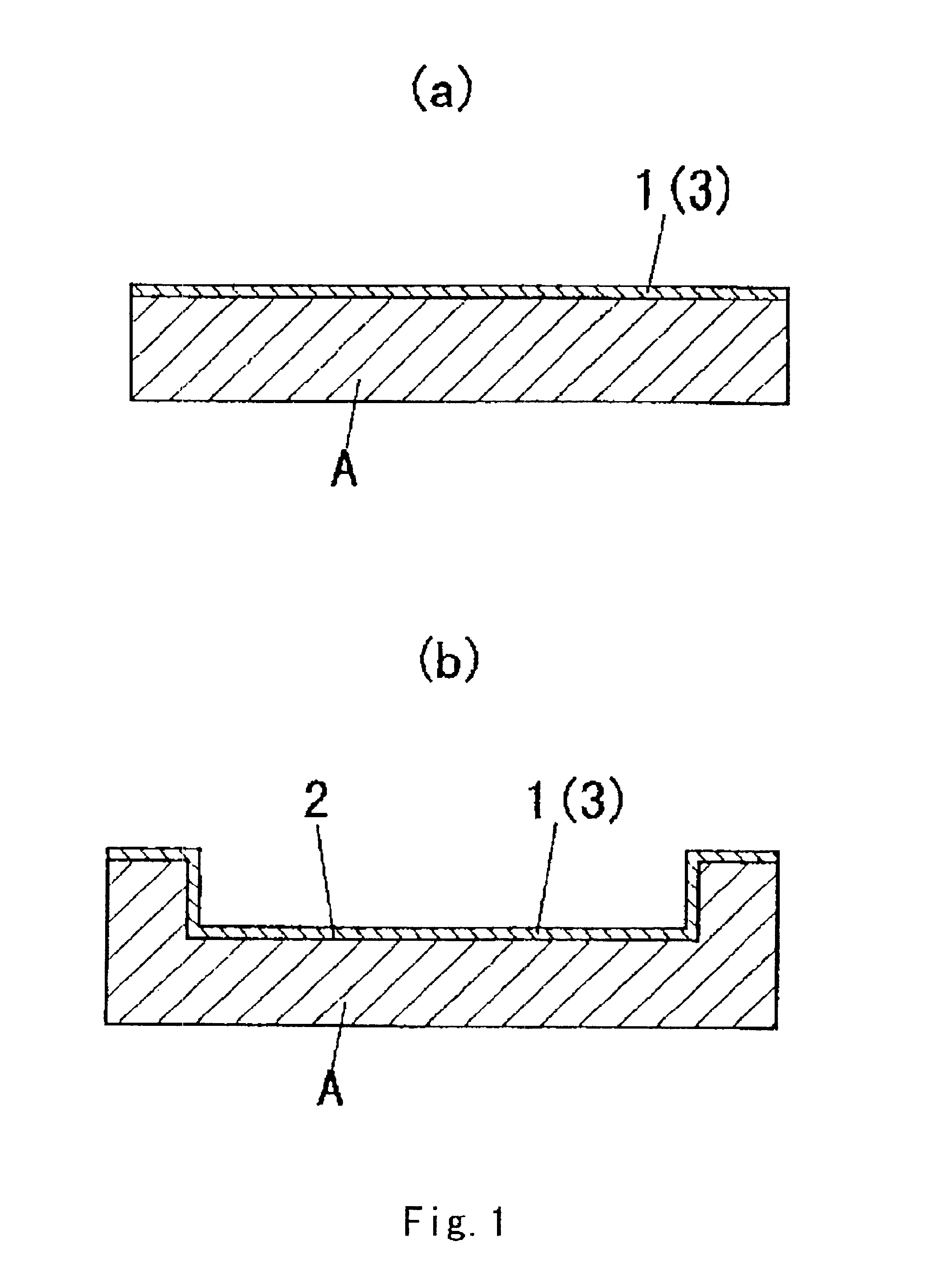
[0066]Using PPA as the base resin, 3 parts in mass of the above-described A as rubber-like elastic material were mixed with to 100 parts in mass of the base resin. This was melted and kneaded at a screw rotating speed of 150 rpm in a twin-screw vent system with 25 mm in diameter and L / D=25, and after cooling a strand obtained, the strand was pelletized to prepare a resin composition. Then, this resin composition was injection-molded to form the resin molded component.

[0067]The surface of this resin molded component was plasma-treated, and the metal layer was formed by sputtering. That is, the resin molded component was firstly set into the chamber of a plasma treatment apparatus, the chamber inside was evacuated to reduce the pressure to about 10−4 Pa, then N2 was introduced and circulated in the chamber as an active gas, the gas pressure inside the chamber was controlled at 10 Pa, and then, 300W power high-frequency voltage (RF: 13.56 MHz) was applied to the electrodes for 30 secon...

examples 2 to 7

, Comparative Examples 4, 6

[0069]Using the base resin shown in Table 1, the rubber-like elastic material shown in Table 1 was mixed by the ratio shown in Table 1 to 100 parts in mass of the base resin. By kneading these in the same manner as Example 1, the resin composition was prepared. From this resin composition, the resin molded component was formed in the same manner as Example 1 and the metal layer was further formed on the surface of the resin molded component.

example 8

[0070]Using the base resin shown in Table 1, the rubber-like elastic material shown in Table 1 was mixed by the ratio shown in Table 1 to 100 parts in mass of the base resin, and further, for the crystal nucleus agent, talc, which is a plate-form inorganic filler, was mixed so that the talc contains 0.7% in mass to the whole resin composition. By kneading these in the same manner as Example 1, the resin composition was prepared. From this resin composition, the resin molded component was formed in the same manner as Example 1 and the metal layer was further formed on the surface of the resin molded component.


PUM

PropertyMeasurementUnit
lengthaaaaaaaaaa
diameteraaaaaaaaaa
diameteraaaaaaaaaa

Abstract

A resin molded component, comprising metal coating treatment being provided on the surface by a physical deposition method chosen from among sputtering, vacuum deposition, and ion plating after the surface is activated by plasma treatment, and is produced by forming a resin composition combined a base resin comprising of a thermoplastic resin or a thermosetting resin with a rubber-like elastic material.

Description

BACKGROUND OF THE INVENTION[0001]1. Field of the Invention[0002]The present invention relates to a resin molded component whose surface is coated with metal by physical deposition method for practical use.[0003]2. Description of the Related Art[0004]Printed circuit boards such as MID, sensor parts, reflectors and the like are manufactured by fabricating a resin molded component by injection-molding a resin composition, and by coating the surface of the resin molded component with a metal layer serving as circuits and reflecting films by physical deposition method such as sputtering, vacuum evaporation, and ion plating.[0005]The resin composition that forms the resin molded component comprises of a thermosetting resin or a thermoplastic resin, and the resin molded component generally provides a low adhesion to metal. In particular, when the metal layer is formed on the surface of the resin molded component by the physical deposition method which is a dry method such as sputtering, va...

Claims


Application Information

Patent Timeline
Patent Type & Authority Patents(United States)
IPC IPC(8): C08L51/00C08L51/06C08L55/00C08L55/02C23C14/02C23C14/20H05K1/03H05K3/38C08J7/06
CPCC08L51/06C23C14/022C23C14/20H05K1/0373C08L55/02Y10T428/251H05K3/381H05K3/388H05K2201/0129H05K2201/0133H05K2201/0209H05K2201/0245H05K2201/0251H05K2201/09118H05K2203/095Y10T428/259Y10T428/25Y10T428/258Y10T428/252Y10S428/901C08L2666/14C08L2666/02H01L2224/05553H01L2224/32225H01L2224/45144H01L2224/48091H01L2224/48227H01L2224/49175H01L2224/73265Y10T428/249951Y10T428/31533Y10T428/31681Y10T428/31699H01L2924/00014H01L2924/00C08J7/06
Inventor IKEGAWA, NAOTOSATO, MASAHIROKONDO, NAOYUKI
Owner MATSUSHITA ELECTRIC WORKS LTD
Why Eureka
Try Eureka