
Guide wire

a technology of guide wire and proximal end, which is applied in the field of guide wire, can solve the problems of affecting the stability of the guide wire, so as to achieve the effect of preventing sharp kinking (sharp bending), enhancing joint strength at the welded portion, and preventing stress concentration on the welded portion

Inactive Publication Date: 2006-10-19
TERUMO KK
View PDF32 Cites 9 Cited by
  • Summary
  • Abstract
  • Description
  • Claims
  • Application Information

AI Technical Summary

Benefits of technology

[0024] Preferably, a resin coating layer formed of a resin material capable of reducing friction is provided at the outer periphery of the second wire.
[0062] Where a resin coating layer, particularly, a resin coating layer formed of a material capable of reducing friction is provided, the sliding performance of the guide wire in a catheter or the like is enhanced, and the steerability of the guide wire is further enhanced. With the sliding resistance of the guide wire reduced, it is possible to prevent more securely a kinking or torsion of the guide wire, particularly,.a kinking or torsion in the vicinity of the welded portion. In the case where a resin coating layer formed of a material rich in flexibility is provided at the outer periphery of the first wire, particularly where the distal end of the first wire is covered with the resin coating layer instead of being exposed, damaging of a blood vessel inside wall or the like can be prevented more assuredly from occurring at the time of insertion of the guide wire into a blood vessel or the like, so that safety can be further enhanced.

Problems solved by technology

This configuration, however, has tended to loose the flexibility at a distal end portion of the guide wire.
On the other hand, when a material having a comparatively low elastic modulus is used for the core member in order to obtain flexibility at a distal end portion of the guide wire, the steerability on the proximal side of the guide wire is lost.
Thus, it has been considered to be difficult to simultaneously obtain both the flexibility and the steerability required.
In addition, the guide wire used in the procedure by way of an endoscope is used under bad conditions such as the curving of the endoscope in a body lumen, the bending of the guide wire on the forceps riser base, and the exchange with a catheter in the condition where a contrast medium is firmly adhered, so that the touque response and the pushability of the guide wire would be spoiled.
As the outside diameter becomes smaller, however, the rigidity of the guide wire is lowered, and the touque response and the pushability are lowered, making it difficult to guide each treatment device to a target site.

Method used


Image

  • Guide wire
  • Guide wire
  • Guide wire

Examples


Embodiment Construction

[0078] The guide wire according to the present invention will be described in detail below, based on preferred embodiments shown in the accompanying drawings.

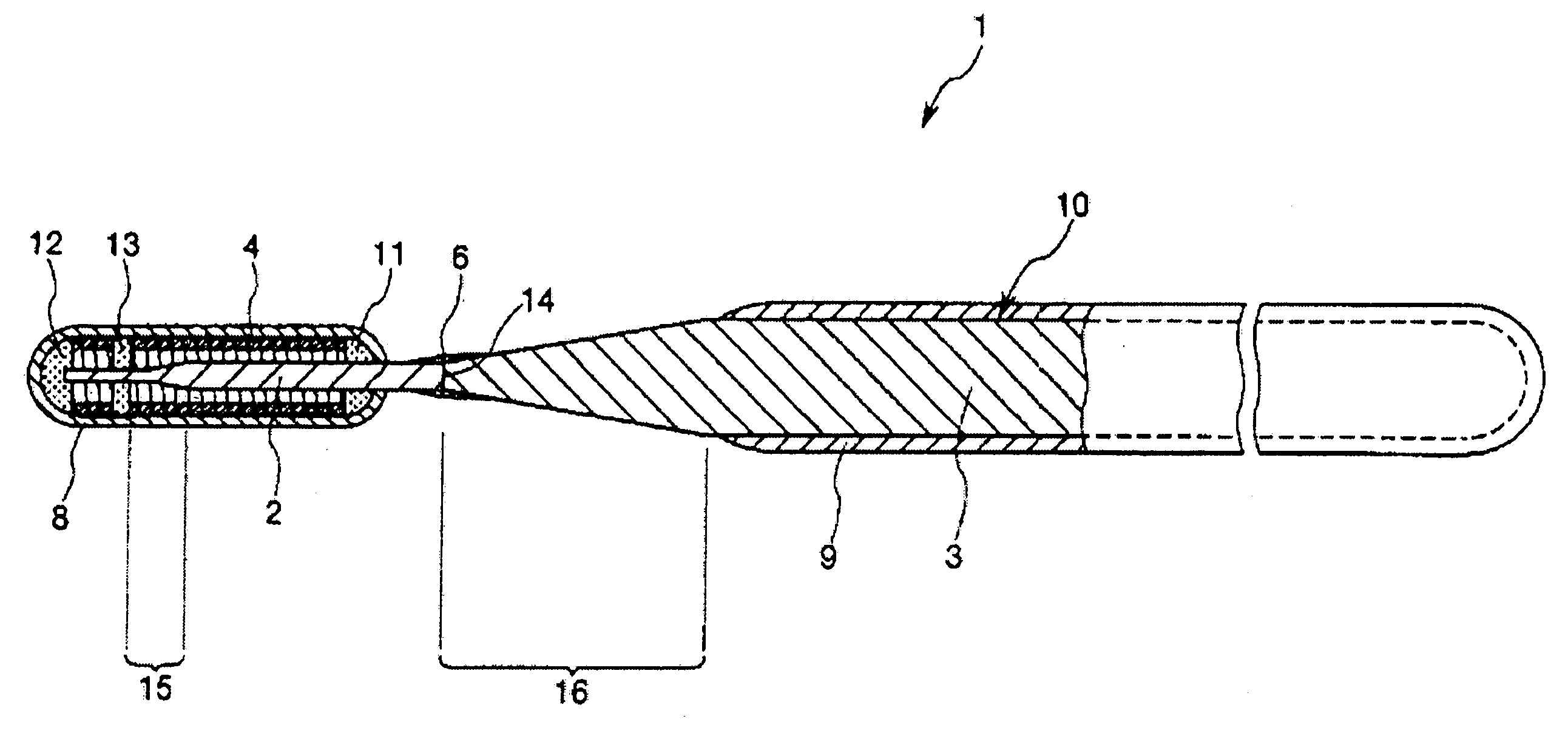
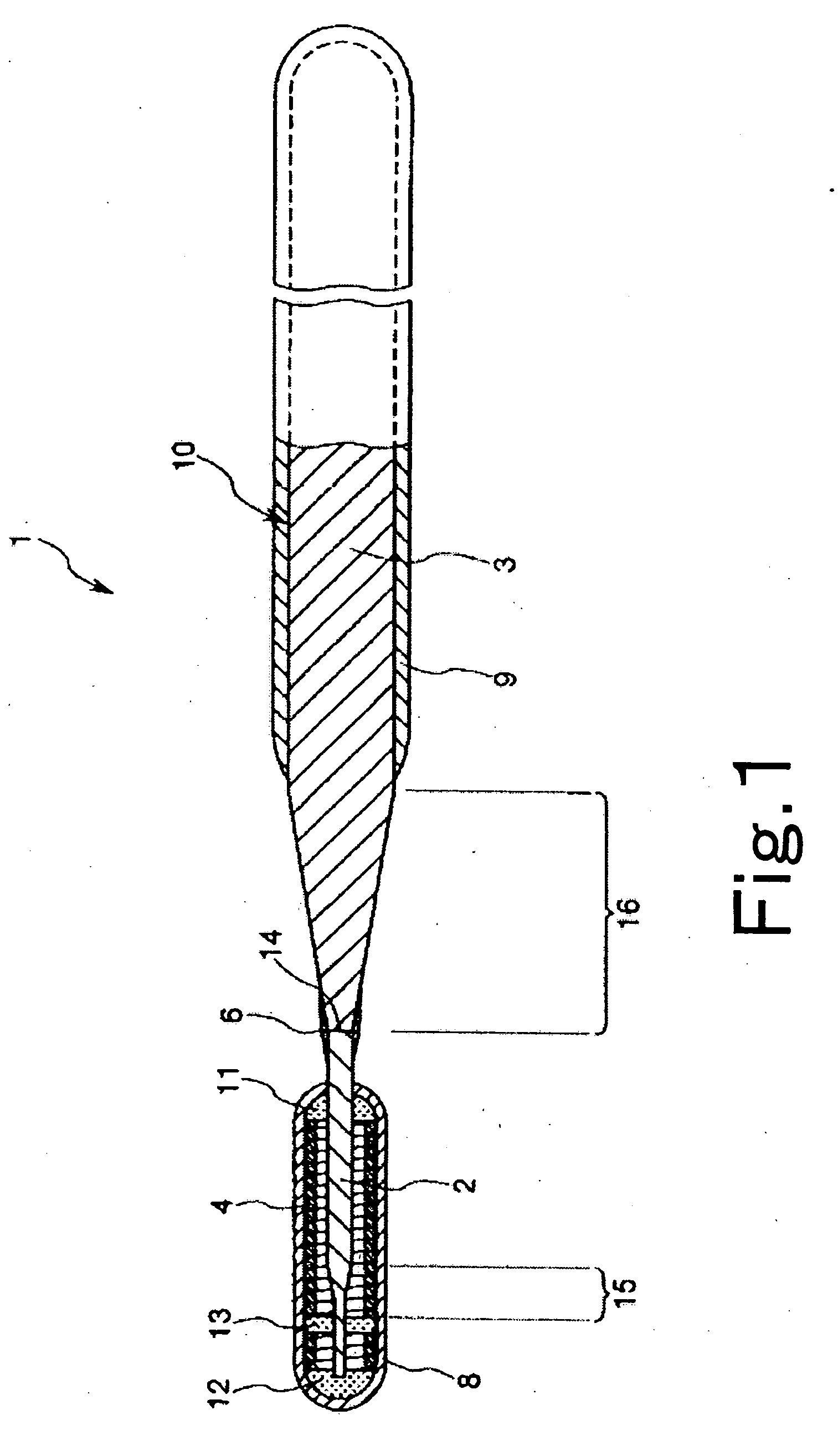
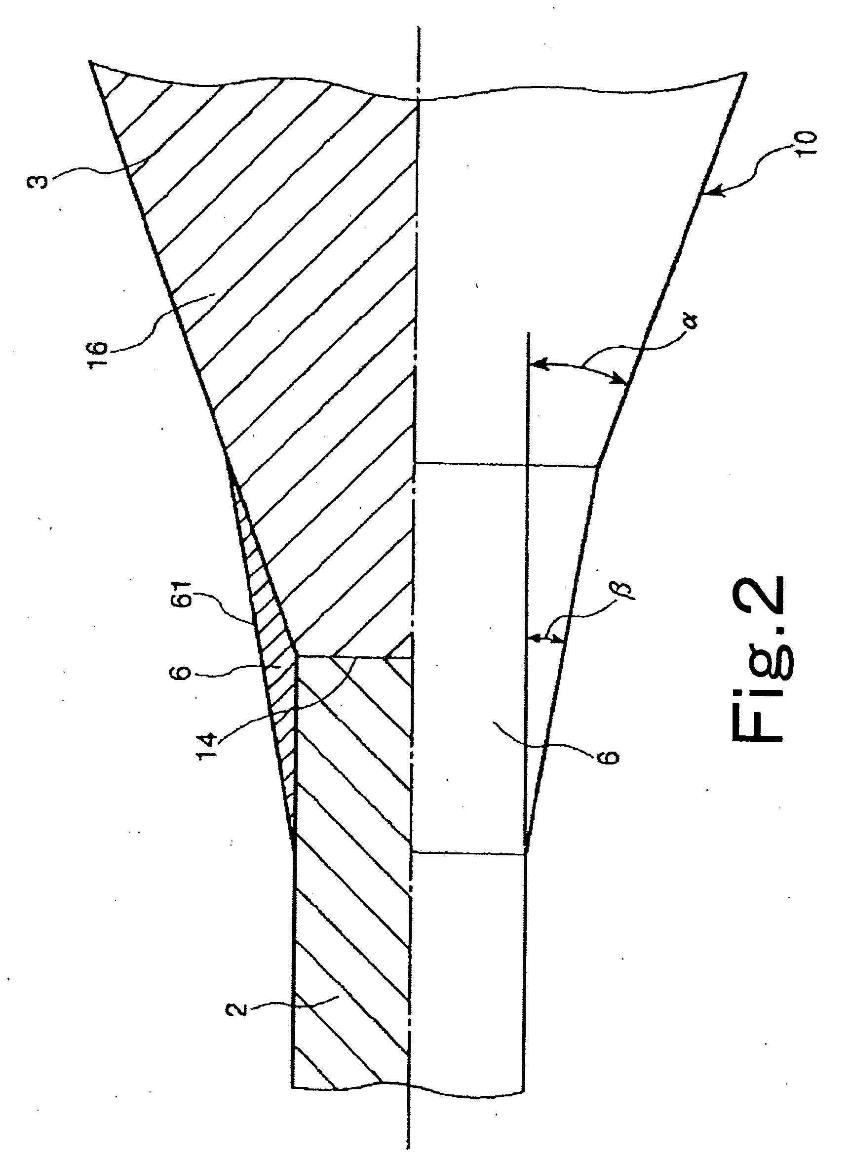
[0079]FIG. 1 is a vertical sectional view showing an embodiment of the guide wire according to the present invention, and FIG. 2 is a vertical sectional view showing in an enlarged form the vicinity of a joined portion of a wire body in the guide wire according to the present invention. Incidentally, for convenience of description, the right side in FIGS. 1 and 2 is referred to as “the proximal end (proximal side)”, and the left side as “the distal end (distal side)”. Besides, in FIGS. 1 and 2, for easy understanding, the guide wire is schematically shown by shortening the guide wire in the longitudinal direction and exaggerating the guide wire in the transverse direction. Therefore, the ratio of size in the longitudinal direction to the size in the transverse direction is different from the real ratio.

[0080] The guide wire 1...


PUM


Abstract

A guide wire has a wire body which includes a first wire, and a second wire disposed on the proximal side of the first wire and joined to the first wire. A radiopaque coil is preferably disposed around a distal end portion of the first wire. Preferably, a proximal end portion of the first wire is substantially constant in outside diameter along the longitudinal direction, while a distal end portion of the second wire may be composed of a tapered portion of which the outside diameter is gradually increased in the proximal direction from the distal end thereof. Both the wires may be joined their end faces. The outer periphery of the joined portion is preferably provided thereon with a coating layer.

Description

BACKGROUND OF THE INVENTION [0001] The present invention relates to a guide wire, particularly to a guide wire used in introducing a catheter into a body lumen such as a blood vessel and a bile duct. [0002] Guide wires are used to guide a catheter in treatment of cites at which open surgeries are difficult or which require low invasiveness to the body, for example, PTCA (Percutaneous Transluminal Coronary Angioplasty), or in examination such as cardioangiography. A guide wire used in the PTCA procedure is inserted, with the distal end projecting from the distal end of a balloon catheter, into the vicinity of a target angiostenosis portion together with the balloon catheter, and is operated to guide the distal end portion of the balloon catheter to the target angiostenosis portion. [0003] Furthermore, a guide wire is used, in treatment of a lesion portion of the bile duct or pancreatic duct, to guide each of various treatment devices to the vicinity of the lesion portion of the bile ...

Claims


Application Information

Patent Timeline
Patent Type & Authority Applications(United States)
IPC IPC(8): A61M25/00
CPCA61M25/09A61M2025/09075A61M2025/09083A61M2025/09166A61M2025/09108A61M2025/09133A61M2025/0915A61M2025/09091
Inventor TANO, YUTAKAUMENO, AKIHIKO
Owner TERUMO KK
Learn More