Lithium Ion Battery

a technology ion battery, which is applied in the field of lithium ion battery, can solve the problems of limited anti-deformation ability of electrode materials, poor mechanical properties, and easy loss of electrode materials by current collectors, and achieves improved utilization of active materials, improved surface area density and energy density of electrodes, and closer stacking

Inactive Publication Date: 2013-09-26
LONG POWER SYST SUZHOU
View PDF3 Cites 16 Cited by
  • Summary
  • Abstract
  • Description
  • Claims
  • Application Information

AI Technical Summary

Benefits of technology

[0019]In the abovementioned lithium ion battery, the cathode or the anode layer comprises the current collector and the electrode active material. The current collector connects with the electrode active material through its three-dimensional network such that active materials' utilization is improved and relatively a high area density and energy density of the electrode is obtained. In addition, the current collector containing the electrode material tis coated with a porous ionic conductive polymer binder such that closer stack with other electrodes and lower cell impedance is achieved; Furthermore, the porous ionic conductive polymer binder can prevent the electrode material peeling off from the current collector.

Problems solved by technology

There are several disadvantages for such a fabrication process: (1) less loading of the electrode active materials due to more binder used and more current collector volume occupied yields to a lower area density of electrode active materials; (2) relatively weak binding between the electrode materials and the smooth surface of the current collector causes poor mechanical properties and limited anti-deformation capability of the electrode materials during the fabrication process and furthermore the electrode materials are prone to lose from the current collector.
Accordingly, the lithium ion batteries made by such a traditional process usually have less satisfactory electrochemical performances such as low capacity, high impedance, and short cycle life.
Furthermore, it also delivers high production cost and low production yield.
Consequently, the accumulated stress could peel the electrode materials off from the current collector and the active materials lose close contact with each other and with the current collector.
Accordingly, the cell impedance grows with the cycling and poor cycling performance is obtained.
However, thick coating brings to poor processability of the electrodes; multilayer stacks create high cell impedance and poor cycling performance.
Furthermore, both of which lead to a high production cost.
On the other hand, the traditional battery fabrication includes multiple steps which are correlated with each other and this yields to great difficulty for process and performance optimization such as cell impedance, cycle life, capacity and energy density and so on.
Thick coating layers further bring to low mechanical properties of the electrode and the electrode materials are prone to peel off from the current collector or just crack.
Therefore the construction and shape of the battery products by such a traditional method are restricted, particularly for the wounded cells.

Method used


Image

  • Lithium Ion Battery
  • Lithium Ion Battery

Examples


example 1

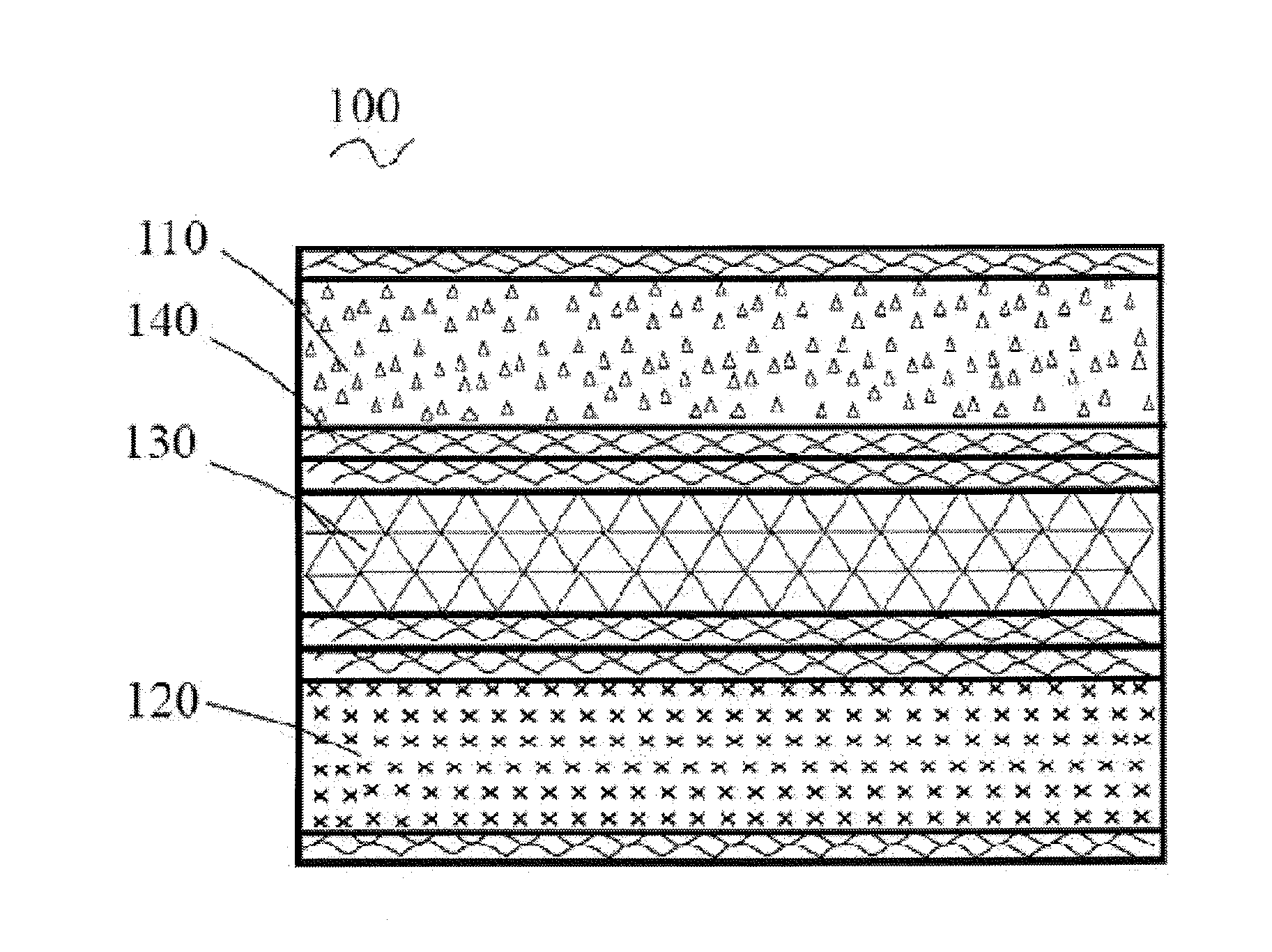
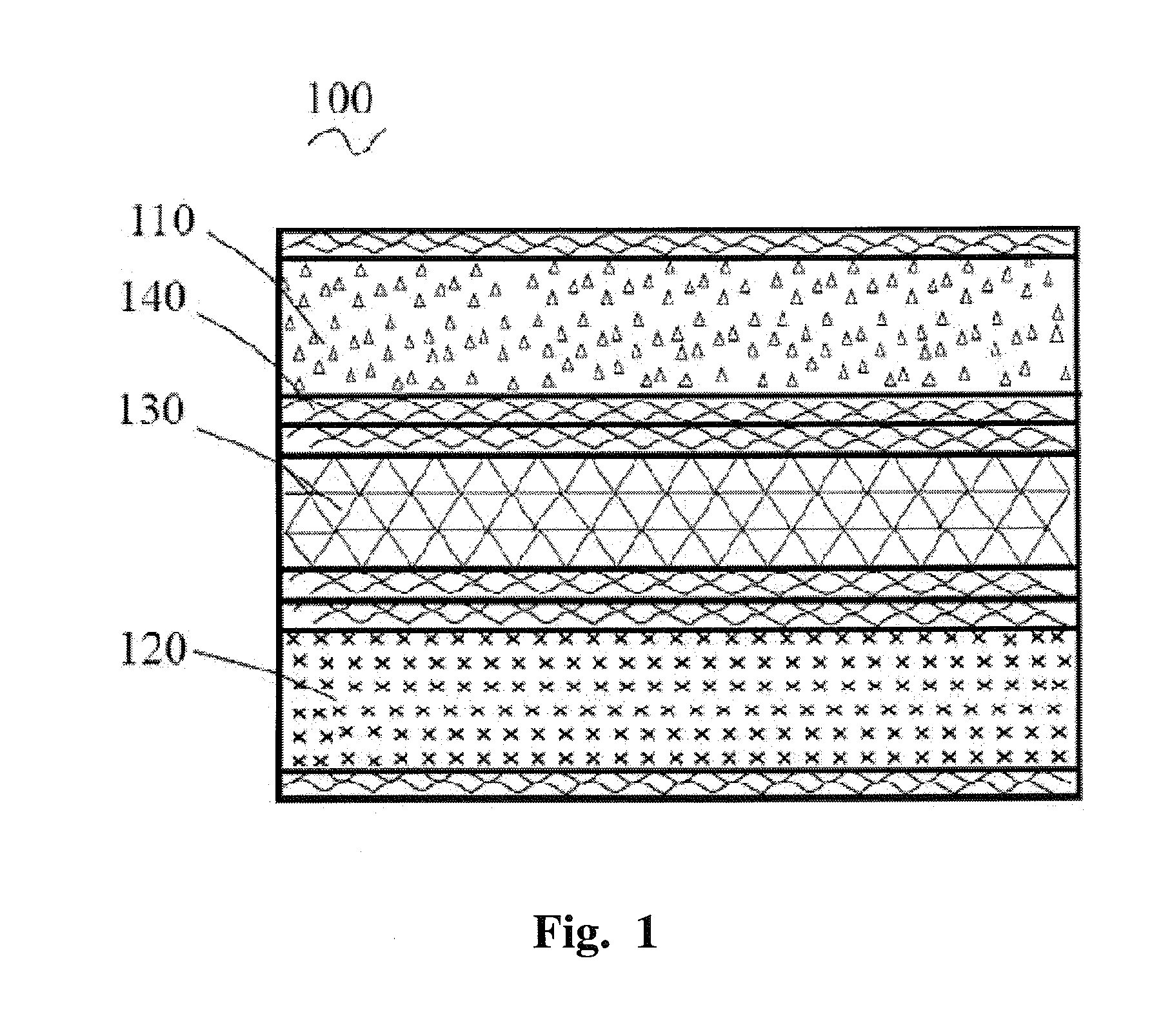
The Fabrication of a Lithium Ion Battery

[0038]Step 1. 7 g PVDF binder is added into 180 g NMP solvent and mix them thoroughly to form the glue like solution.

[0039]Step 2. The cathode slurry is prepared by the following process: The 140 g LiFePO4 and 2.8 g Super-P conductive carbon is thoroughly mixed into the above glue like solution, mix them thoroughly in the mixer to form a paste like cathode slurry. Use the foamed aluminum with the porosity of 90% as the current collector. Use a doctor blade to coat the cathode slurry onto the both sides of the foamed Al current collector. Put the electrode slurry coated current collector into 110° C. vacuum oven for 4 hrs to remove NMP solvent and dry it. Press the above dried current collector with a rolling press machine to make the active material packed tighter. The targeted thickness after pressing is determined by the battery design, generally at 500 μm including the current collector imbedded inside the electrode material. Calcine the pr...


PUM

PropertyMeasurementUnit
porosityaaaaaaaaaa
viscosityaaaaaaaaaa
volume changeaaaaaaaaaa

Abstract

The present invention is related with a novel fabrication technique for a lithium ion battery, consisting of a cathode layer and an anode layer. The cathode and the anode layer are configured through a separator in between. The cathode or the anode layer comprises: a current collector with porous three-dimensional network construction; an electrode active material, filled in the pores and onto the both sides of the abovementioned current collector; and a layer of porous ionic conductive polymer layer, coated on the abovementioned current collector holding the electrode material. In the abovementioned lithium ion battery, the cathode or the anode layer comprises both the current collector and the electrode material. The current collector connects with the electrode material through its porous three-dimensional network and thus improves the active material utilization, capacity and energy density of the lithium ion battery.

Description

TECHNICAL FIELD[0001]The present invention relates to a lithium ion battery field. More particularly, it relates to a novel lithium ion battery technology.BACKGROUND OF THE INVENTION[0002]The traditional lithium ion battery comprises at least one pair of cathode and anode layers. The cathode and the anode layer are configured through a separator in between. The fabrication process for the cathode and the anode is usually as follows: the electrode material is coated on the solid metal foil through a binder. There are several disadvantages for such a fabrication process: (1) less loading of the electrode active materials due to more binder used and more current collector volume occupied yields to a lower area density of electrode active materials; (2) relatively weak binding between the electrode materials and the smooth surface of the current collector causes poor mechanical properties and limited anti-deformation capability of the electrode materials during the fabrication process a...

Claims


Application Information

Patent Timeline
Patent Type & Authority Applications(United States)
IPC IPC(8): H01M4/76H01M50/417
CPCH01M4/762H01M2/1653H01M4/0404H01M4/505H01M2/168H01M4/745H01M4/80H01M10/0525H01M10/058H01M4/5825Y02E60/10H01M50/461H01M50/417
Inventor HUANG, BIYING
Owner LONG POWER SYST SUZHOU
Why Eureka
Try Eureka