Endoscope

a technology of endoscope and endoscope, which is applied in the field of endoscope, can solve the problems of increased heat from the image sensor, unstable operation of the image sensor, and deterioration of image quality, and achieve the effect of low manufacturing cos

Inactive Publication Date: 2013-09-26
FUJIFILM CORP
View PDF22 Cites 53 Cited by
  • Summary
  • Abstract
  • Description
  • Claims
  • Application Information

AI Technical Summary

Benefits of technology

[0008]An object of the present invention is to provide an endoscope provided with a lightweight, downsized, and inexpensive heat dissipation mechanism.
[0019]Because the heat dissipation mechanism does not employ a large-sized heavy member, the heat dissipation mechanism is lightweight and downsized, and produced with low manufacture cost.

Problems solved by technology

As a result, heat from the image sensor is increased.
An excessive increase in the temperature of the distal portion due to the heat from the image sensor makes the operation of the image sensor unstable.
This causes noise in an image signal from the image sensor, resulting in deterioration of the image quality.
In the above-described endoscopes, the heat dissipation mechanisms are composed of the large-sized members, which increase material cost.
The large-sized heat dissipation mechanism makes the insert section of the endoscope large in diameter and heavy.

Method used


Image

  • Endoscope
  • Endoscope
  • Endoscope

Examples


first embodiment

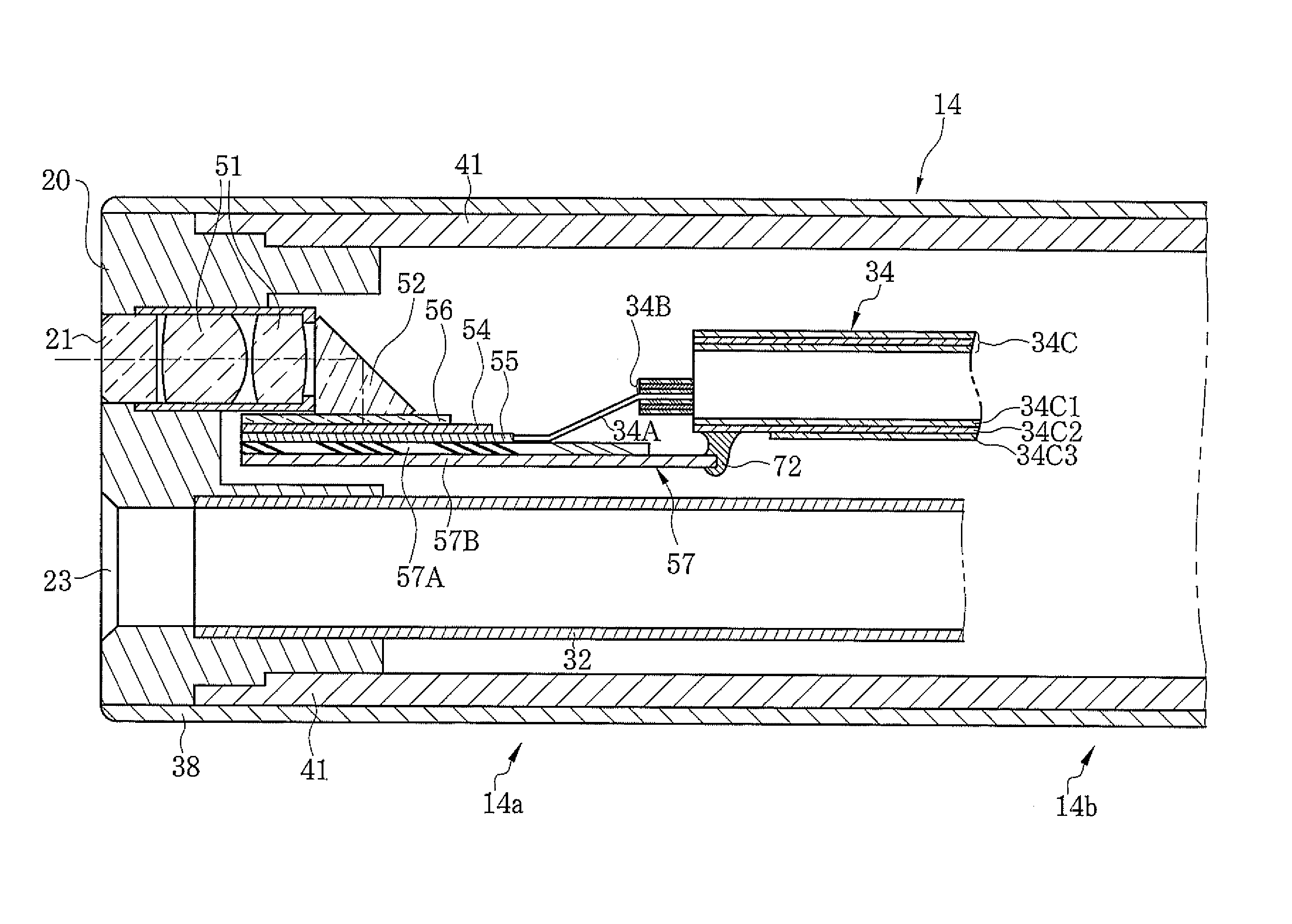
[0038]The distal portion of the endoscope 10 according to the present invention incorporates the imaging section. As shown in FIG. 4, the imaging section is provided with an objective optical system 51, a prism 52, and an image sensor 54. Image light of the region of interest captured through the capture window 21 is incident on the prism 52 through the objective optical system 51. The prism 52 refracts the image light from the objective optical system 51 in a substantially vertical direction, and thereby forms an image of the region of interest on an imaging surface of the image sensor 54. The image sensor 54 is a CCD image sensor, a CMOS image sensor, or the like, and generates an image signal into which an image is converted photoelectrically. The image signal is outputted through a circuit board 55 provided on the opposite side of the imaging surface that is parallel (or substantially parallel) with a direction of insertion of the insert section 14. The circuit board 55 is elect...

second embodiment

[0049]Next, referring to FIG. 6, an endoscope according to the present invention is described. A heat dissipation substrate 75 is disposed on the opposite side of the imaging surface of the image sensor 54 through the circuit board 55 such that a plane direction of the heat dissipation substrate 75 is parallel with (or substantially parallel with) the image sensor 54. The heat dissipation substrate 75 is provided with first to third high thermal conductive layers 75A, 75B, and 75C. The first high thermal conductive layer 75A is sandwiched by the second and third high thermal conductive layers 75B and 75C. In this embodiment, the first high thermal conductive layer 75A is made from electrically insulating and thermally conductive material. Each of the second and third high thermal conductive layers 75B and 75C is made from material with good thermal conductivity. The first to third high thermal conductive layers 75A, 75B, and 75C are adhered together with an adhesive. Note that, like...


PUM


Abstract

An endoscope comprises an image sensor incorporated in a distal portion of an insert section to be inserted in a body cavity, a heat dissipation substrate, a multi-core cable, and a connection member. The heat dissipation substrate is attached to the back of a circuit board that supports the image sensor. The multi-core cable has signal lines and a second shield member. The signal lines, each covered with a first shield member, transmit signals to / from the image sensor. The second shield member covers and holds the signal lines together. The second shield member has an electrically conductive layer. The connection member transmits heat, generated in the image sensor, from the heat dissipation substrate to the second shield member.

Description

BACKGROUND OF THE INVENTION[0001]1. Field of the invention[0002]The present invention relates to an endoscope comprising a heat dissipation mechanism of an image sensor.[0003]2. Description Related to the Prior Art[0004]Diagnoses and operations using endoscopes have been widely performed in medical field. The endoscope is provided with an insert section to be inserted into a body cavity of a patient and a handling section provided at a proximal end of the insert section. A distal portion of the insert section incorporates an image sensor for imaging a region of interest in the body cavity.[0005]In the distal portion of the insert section, heat generated in the image sensor and the like accumulates and raises the temperature of the insert section. Recently, pixel number and speed of reading image signals have been increased due to a demand to improve image quality of endoscopic images. As a result, heat from the image sensor is increased. An excessive increase in the temperature of t...

Claims


Application Information

Patent Timeline
Patent Type & Authority Applications(United States)
IPC IPC(8): A61B1/12
CPCA61B1/128A61B1/051
Inventor TAKAHASHI, KAZUAKI
Owner FUJIFILM CORP
Why Eureka
Try Eureka