
Flower catheter for mapping and ablating veinous and other tubular locations

a catheter and catheter technology, applied in the field of catheters for mapping and ablating veinous and other tubular locations, can solve the problems of aberrant activity, difficult to manipulate and control the distal end of a straight catheter, and formation of a lesion within the cardiac tissue which is electrically non-conductiv

Active Publication Date: 2013-09-26
BIOSENSE WEBSTER (ISRAEL) LTD
View PDF9 Cites 95 Cited by
  • Summary
  • Abstract
  • Description
  • Claims
  • Application Information

AI Technical Summary

Benefits of technology

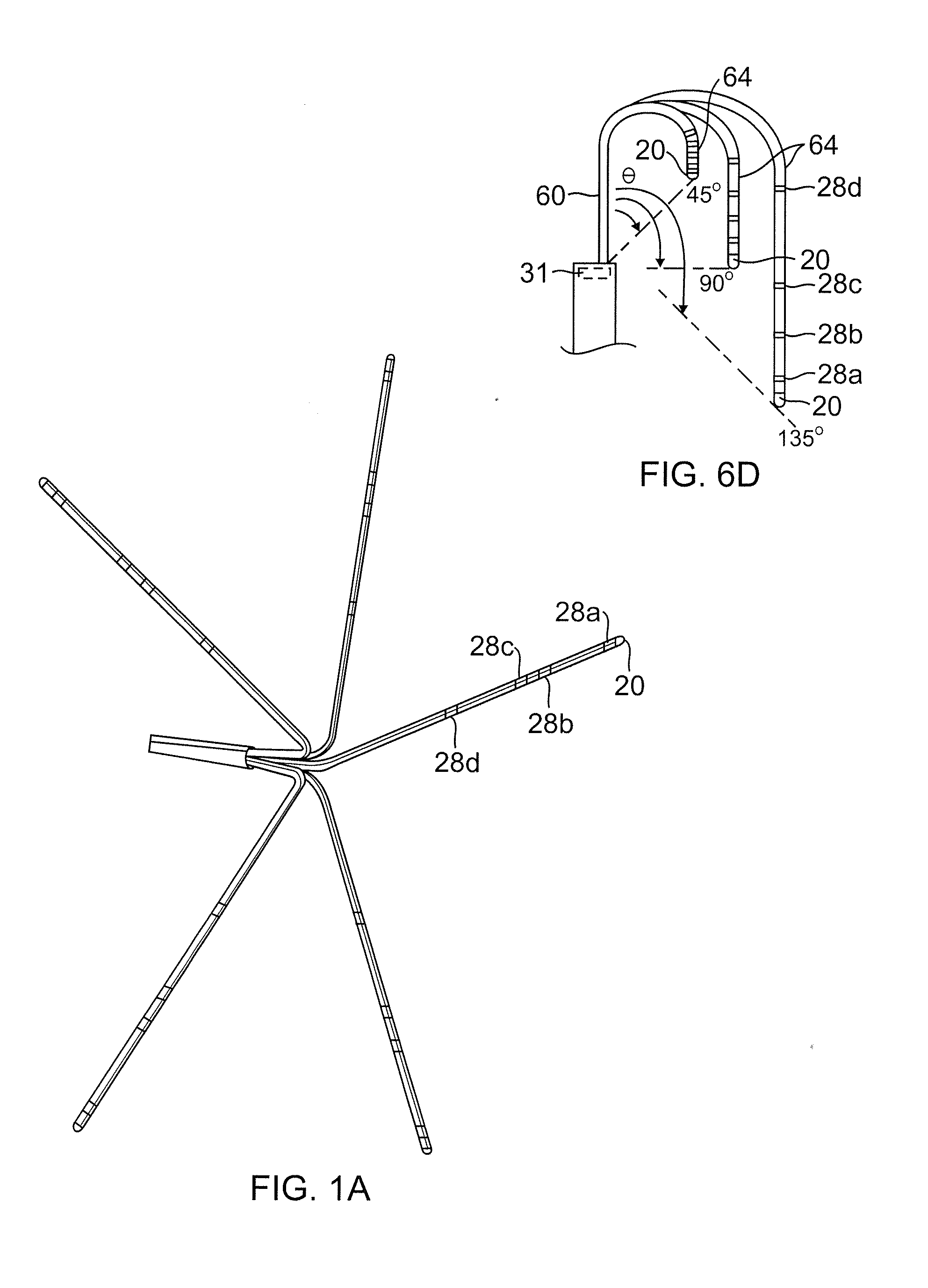
The present invention is a catheter for ablating areas near the heart that has a plurality of spines that can adapt to different shape of the tubular region being treated. Each spine has a straight proximal portion and a generally L-shaped distal portion that converts to a U-shaped configuration for better contact with the surrounding tissue. The catheter can have a tip electrode and a ring electrode on each spine, which can make simultaneous contact with the heart tissue along two different inner circuits of the tubular region. The technical effects of this invention are improved contact between the catheter and the surrounding tissue, allowing for more efficient ablation of the heart tissue and better mapping of the cardiac electrical activity.

Problems solved by technology

The tissue is heated sufficiently to cause cellular destruction in the cardiac tissue resulting in formation of a lesion within the cardiac tissue which is electrically non-conductive.
A disadvantage with current catheters is where the aberrant activity originates in a vein or other tubular structure leading away from the heart chamber.
However, it is difficult to manipulate and control the distal end of a straight catheter so that it effectively ablates about the circumference.
Flower mapping catheters are known; however, conventional flower catheters carry smaller electrodes which are not well suited for ablation.
However, lasso catheters have a generally circular main portion which is not always adaptable to noncircular tubular structures.
As such, testing the line of isolation for completion requires repositioning the catheter, ire-use of a second catheter, both of which increase the duration, complexity and / or cost of the ablation procedure.

Method used


Image

  • Flower catheter for mapping and ablating veinous and other tubular locations
  • Flower catheter for mapping and ablating veinous and other tubular locations
  • Flower catheter for mapping and ablating veinous and other tubular locations

Examples


Embodiment Construction

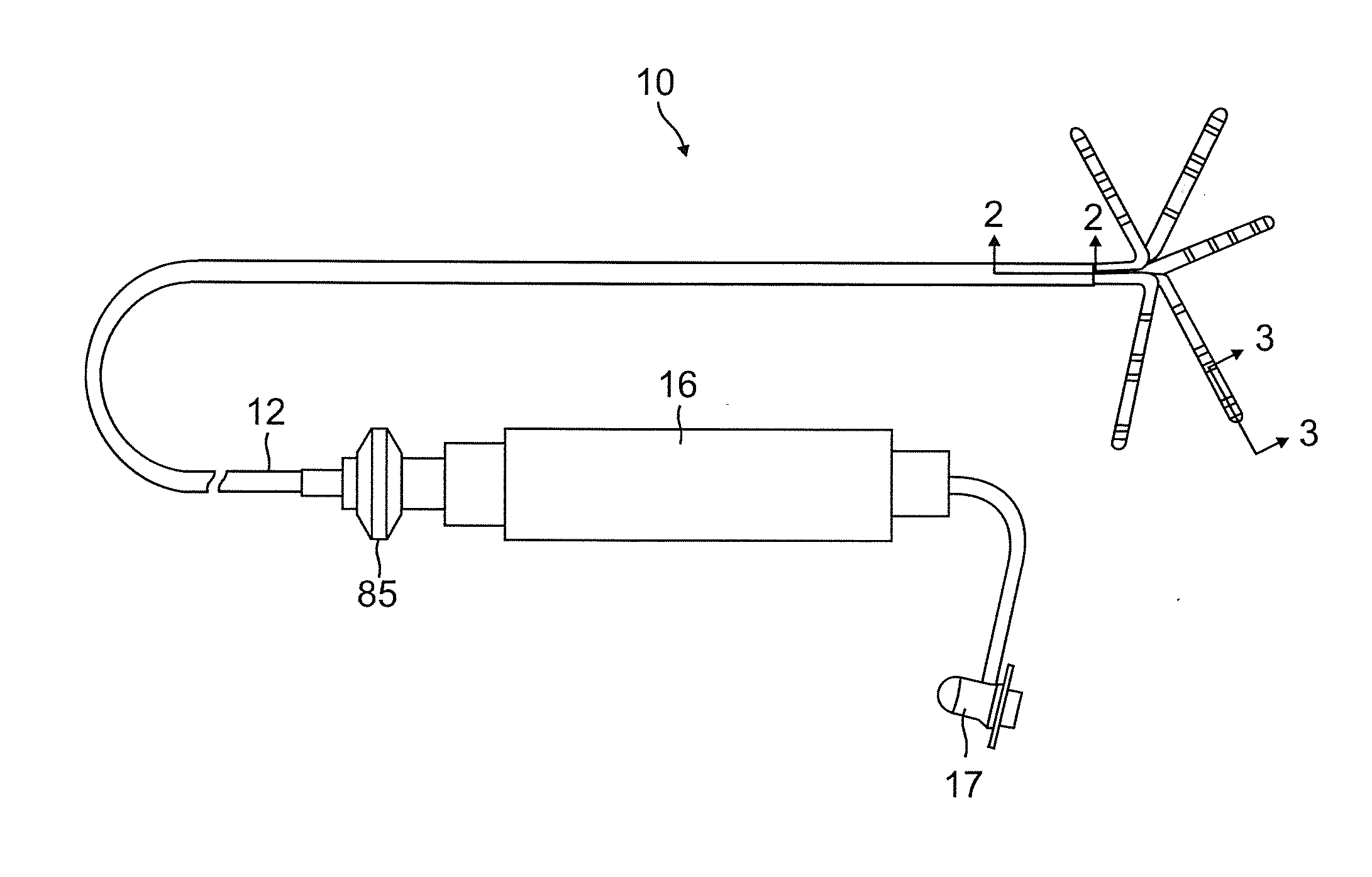
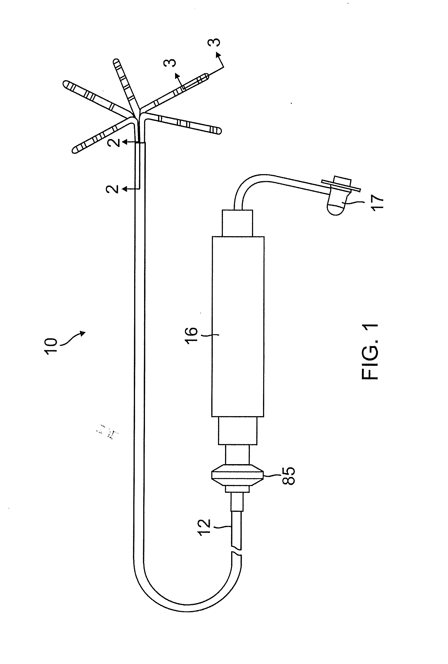
[0035]The invention is directed to a catheter 10 as shown in FIG. 1, having a distal assembly 18 comprising a plurality of spines 14. Each spine carries at least one electrode, preferably a tip electrode 20 and at least one ring electrode 28, such that when the spines are positioned in contact with tissue of a tubular structure at or near the heart, each spine is capable of obtaining electrical data and ablating tissue. As shown in FIG. 1, the catheter 10 comprises an elongated catheter body 12 having proximal and distal ends, a control handle 16 at the proximal end of the catheter body 12, and a distal assembly 18 comprising a plurality of spines 14 mounted at the distal end of the catheter body 12.

[0036]As shown in FIGS. 1 and 2, the catheter body 12 comprises an elongated tubular construction having a single, axial or central lumen 15, but can optionally have multiple lumens along all or part of its length if desired. The catheter body 12 is flexible, i.e., bendable, but substant...


PUM


Abstract

An improved catheter particularly useful for tubular regions at or near the heart has a distal assembly having at least two spines, each having a proximal end fixed to the catheter and a free distal end. Each spine has a support arm supporting the spine in a generally L-shaped configuration when the spine is in a relaxed, neutral state and in a generally U-shaped configuration when the spine is inserted into a tubular region. The spine has a proximal portion and a distal portion that may be straight or curved or zig-zagged. Each spine carries a tip electrode and at least one ring electrode that come into contact simultaneously with heart tissue for ablation and / or sensing electrical activity along two different circumferences of the tubular region simultaneously.

Description

BACKGROUND OF THE INVENTION[0001]Electrode catheters have been in common use in medical practice for many years. They are used to stimulate and map electrical activity in the heart and to ablate sites of aberrant electrical activity. In use, the electrode catheter is inserted into a chamber of the heart. Once the catheter is positioned, the location of aberrant electrical activity within the heart is then located.[0002]One location technique involves an electrophysiological mapping procedure whereby the electrical signals emanating from the conductive endocardial tissues are systematically monitored and a map is created of those signals. By analyzing that map, the physician can identify the interfering electrical pathway. A conventional method for mapping the electrical signals from conductive heart tissue is to percutaneously introduce an electrophysiology catheter (electrode catheter) having mapping electrodes mounted on its distal extremity. The catheter is maneuvered to place th...

Claims


Application Information

Patent Timeline
IPC IPC(8): A61B18/14A61B5/361A61B5/296
CPCA61B18/1492A61B2017/00867A61B2018/1467A61B2018/00839A61B2018/00357A61B2018/00577A61B2218/002A61B5/4848A61B5/6859A61B2018/0016A61B5/287A61B18/12A61B5/283A61B5/25
Inventor FANG, ITZHAK
Owner BIOSENSE WEBSTER (ISRAEL) LTD
Learn More