Supercharge Your Innovation With Domain-Expert AI Agents!

Self-Calibrating Single Track Absolute Rotary Encoder

Active Publication Date: 2013-09-26
MITSUBISHI ELECTRIC RES LAB INC
View PDF1 Cites 13 Cited by
  • Summary
  • Abstract
  • Description
  • Claims
  • Application Information

AI Technical Summary

Benefits of technology

The invention provides a single track, single read-head absolute rotary encoder that can calibrate itself during manufacturing and use. It can compensate for errors caused by environmental or mechanical conditions and also vignetting due to illumination variations. This eliminates the need for multiple read-heads to cancel eccentricity errors, reducing cost and complexity. Additionally, it corrects for other installation errors such as change of gap and shaft wobble.

Problems solved by technology

However, several errors can be introduced in the rotary encoder during manufacturing.
These include errors in the scale pattern, installation of the scale on a rotary shaft, read-head alignment, and noise in electrical circuits.
Another source of errors is eccentricity induced when the scale on a rotary disc is arranged on a rotary shaft In addition, out-of-plane motion (wobble), and misalignment in installation can also lead to variation of the distance between the read-head and the scale.
These factors affect the overall accuracy of rotary encoders.
During operation, temperature variations and mechanical vibrations can cause further distortions, further reducing accuracy.
Vignetting leads to errors in detected zero-crossings (edges), thereby reducing the overall accuracy.
Rotary encoders that use multiple read-heads to reduce eccentricity errors increase the cost of the system and make the system design cumbersome.
Such requirements increase calibration effort and time.

Method used


Image

  • Self-Calibrating Single Track Absolute Rotary Encoder
  • Self-Calibrating Single Track Absolute Rotary Encoder
  • Self-Calibrating Single Track Absolute Rotary Encoder

Examples


Embodiment Construction

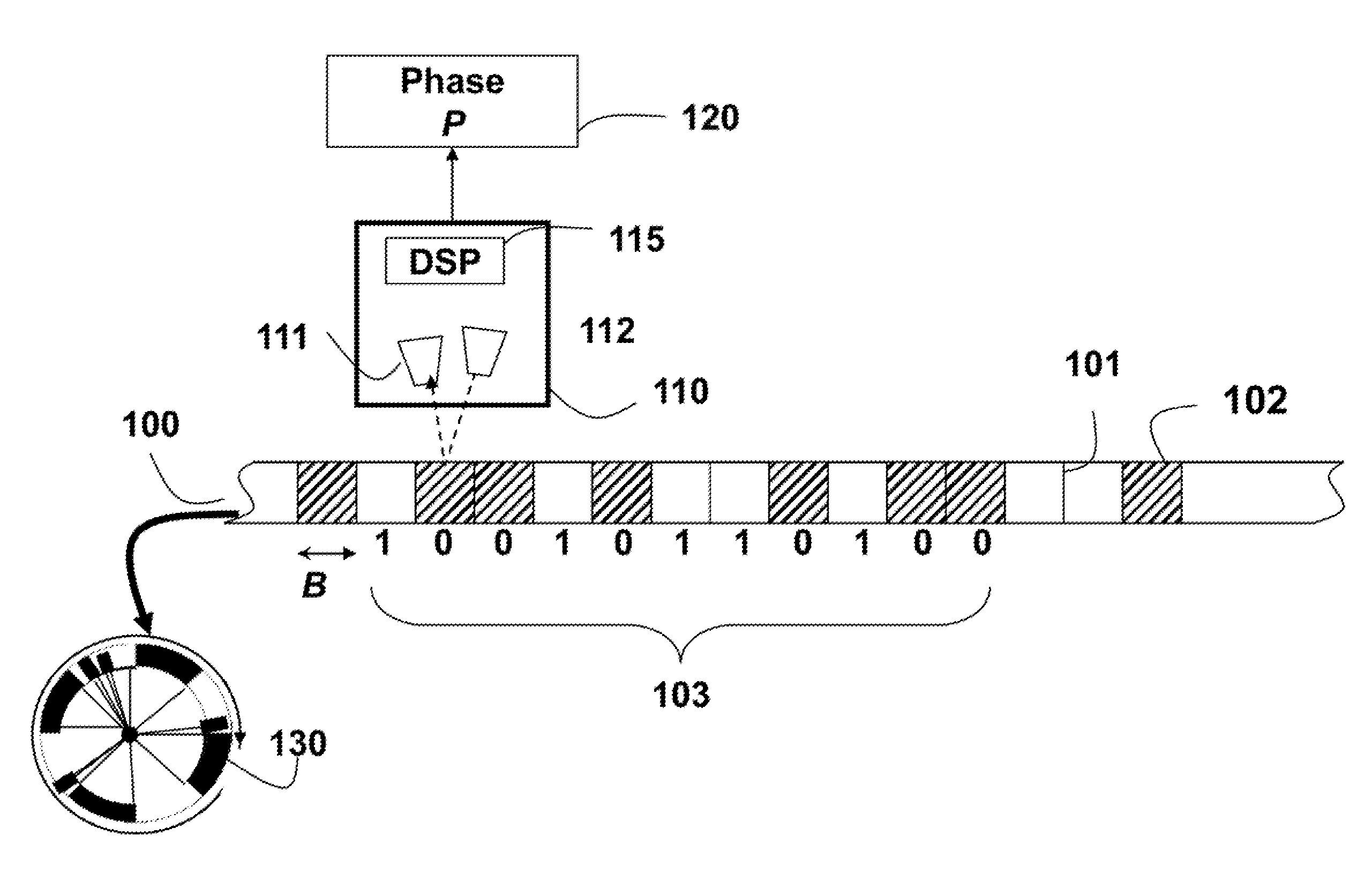
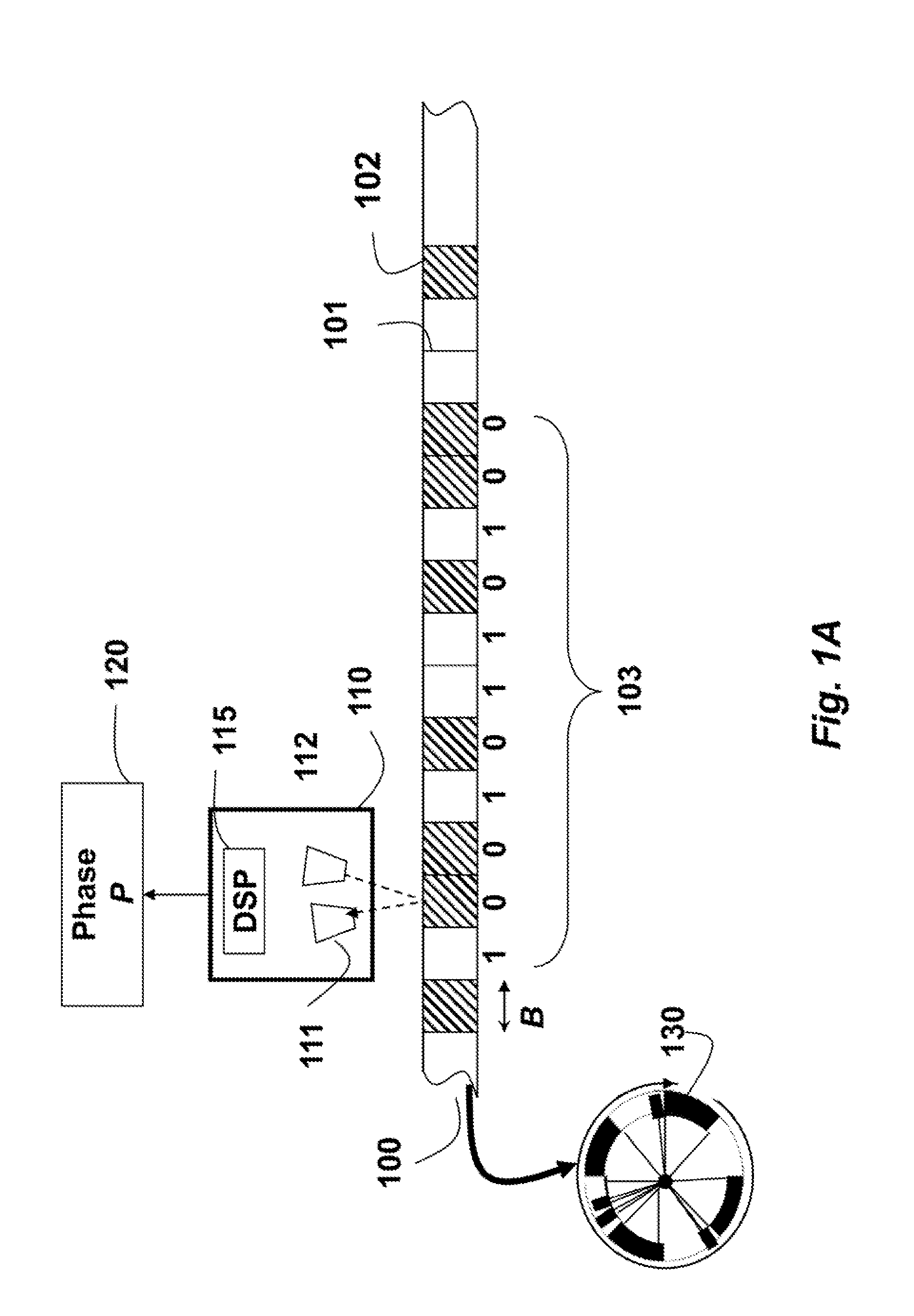
[0029]The embodiments of the invention provide a single track absolute rotary encoder. A read-head can be a linear charge-coupled device (CCD) or a complementary metal-oxide-semiconductor (CMOS) to acquire ID images of a rotating circular scale. The 1D image includes a linear array of pixels. The scale includes reflecting and non-reflecting regions arranged according to a de Bruijn sequence. The de Bruijn sequence is well suited, because the pattern itself is circular in nature.

[0030]Absolute Circular Scale

[0031]FIG. 1 shows a small portion of a circular scale 100 of an absolute encoder for one embodiment of our invention. Details of the scale are described in U.S. application Ser. No. 13 / 100,092. The scale is used to determine a high-resolution phases P 120.

[0032]The scale can include alternate light reflecting 101, and non-reflecting 102 marks or bits. The marks can also alternate between opaque and transparent, depending on a relative position of the light source with respect to ...


PUM


Abstract

A rotary encoder includes a single read-head and a circular scale. The encoder is self-calibrated by acquiring calibration samples with the read-head for rotational angles of the circular scale, and estimating spatial frequency and spatial distortion parameters of the encoder from the calibration samples.

Description

RELATED APPLICATION [0001]This application is a Continuation-in-Part of a parent U.S. application Ser. No. 13 / 367,549, “Method for Estimating Positions Using Absolute Encoders,” filed by Agrawal on Feb. 7, 2012, incorporated herein by reference.FIELD OF THE INVENTION [0002]This invention relates to measuring devices and in particular to absolute rotary encoders for measuring absolute angle of rotation.BACKGROUND OF THE INVENTION [0003]Accurate estimation of linear positions and rotational angles is an important task in industrial automation, and similar applications. Devices, such as numerically controlled (CNC) machines, drill bits, robot arms or laser cutters, and assembly lines need precise measurements. Feedback control is often used for precision measurements.[0004]Typical encoders include a scale and a read-head. Optical encoders are typically used to measure absolute or relative linear positions or rotational angles. Relative encoders measure the relative position or angle wi...

Claims


Application Information

Patent Timeline
IPC IPC(8): G01D18/00
CPCG01D5/2455G01D5/24452G01D18/00G01D5/34792G01D18/001
Inventor AGRAWAL, AMITTHORNTON, JAY
Owner MITSUBISHI ELECTRIC RES LAB INC
Features
  • R&D
  • Intellectual Property
  • Life Sciences
  • Materials
  • Tech Scout
  • Unparalleled Data Quality
  • Higher Quality Content
  • 60% Fewer Hallucinations
Learn More