Eureka AIR delivers breakthrough ideas for toughest innovation challenges, trusted by R&D personnel around the world.

Programmable readout integrated circuit for an ionizing radiation sensor

a technology of ionizing radiation and integrated circuit, which is applied in the direction of radiological control devices, instruments, television systems, etc., can solve the problems of inability to increase the intensity of x-ray, the dynamic range of the x-ray sensor is limited, and the intensity cannot be increased

Inactive Publication Date: 2013-10-03
LUXEN TECH +1
View PDF10 Cites 16 Cited by
  • Summary
  • Abstract
  • Description
  • Claims
  • Application Information

AI Technical Summary

Benefits of technology

This patent describes a computer-implemented method for setting the amplification gain of a pixel array. The method involves receiving an electrical signal from an ionizing radiation source at one or more pixel sensors in the array, setting the amplification gain of the signal by turning a switch on or off, and scanning the array to determine the intensity of the radiation. The method then generates a gain control signal based on the intensity of the radiation. This allows for dynamic adjustment of the amplification gain of the pixel array, improving the accuracy and sensitivity of the detection process.

Problems solved by technology

The dynamic range of the X-ray sensor may be limited.
Therefore, there is no way to increase the intensity of the X-ray.
Thus, when the X-ray is converted into an image, the intensity cannot be increased.
Because of this problem, variations occur among the pixels due to limitation of pixel array readout integrated circuit (ROIC) in the manufacturing process.
Therefore, each pixel data becomes different when the X-ray is received, causing fuzzy images.
Heretofore, several unsuccessful attempts have been made to address these shortcomings.
None of these references, however, teach a readout circuit for increasing the dynamic range of an ionizing radiation sensor.

Method used


Image

  • Programmable readout integrated circuit for an ionizing radiation sensor
  • Programmable readout integrated circuit for an ionizing radiation sensor
  • Programmable readout integrated circuit for an ionizing radiation sensor

Examples


Embodiment Construction

[0033]Illustrative embodiments will now be described more fully herein with reference to the accompanying drawings, in which exemplary embodiments are shown. This disclosure may, however, be embodied in many different forms and should not be construed as limited to the exemplary embodiments set forth herein. Rather, these exemplary embodiments are provided so that this disclosure will be thorough and complete and will fully convey the scope of this disclosure to those skilled in the art. In the description, details of well-known features and techniques may be omitted to avoid unnecessarily obscuring the presented embodiments.

[0034]The terminology used herein is for the purpose of describing particular embodiments only and is not intended to be limiting of this disclosure. As used herein, the singular forms “a”, “an”, and “the” are intended to include the plural forms as well, unless the context clearly indicates otherwise. Furthermore, the use of the terms “a”, “an”, etc., do not de...


PUM


Abstract

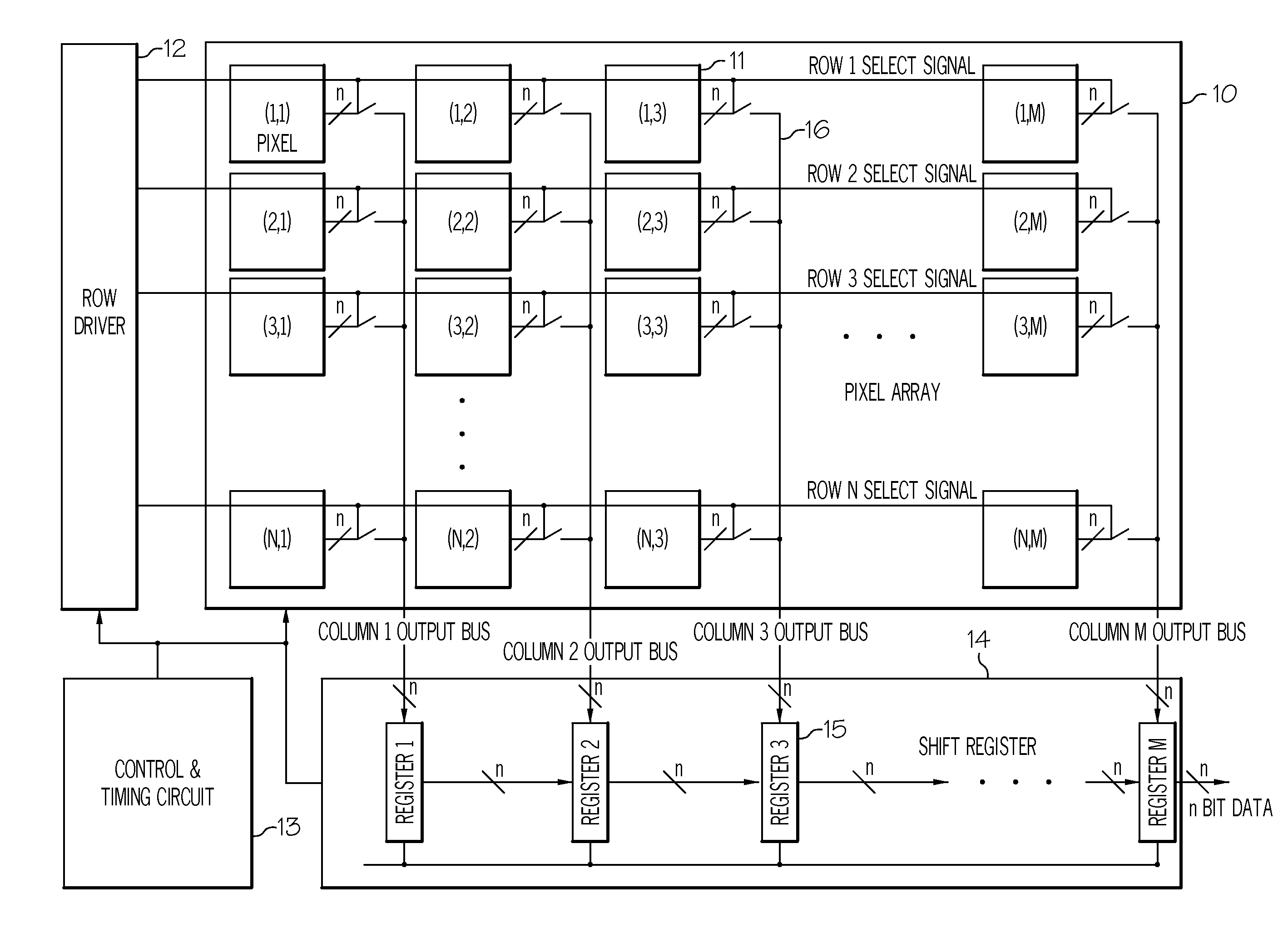
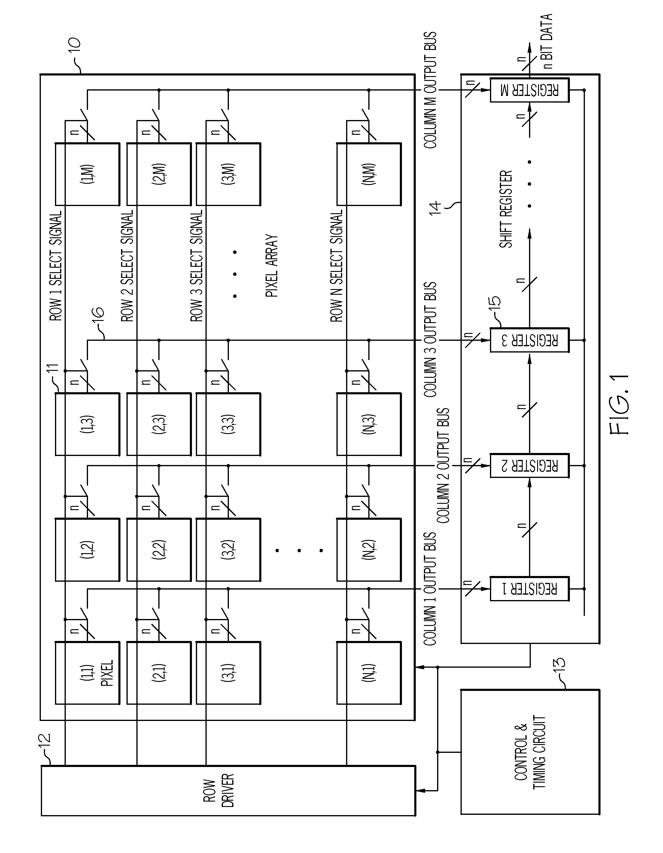
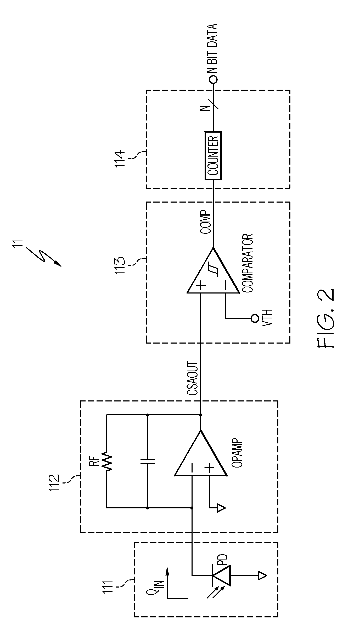
Embodiments of the present invention provide a computer-implemented method for setting an amplification gain of a pixel array. Specifically, among other things, embodiments of the present invention provide a computer-implemented infrastructure comprising: receiving an electrical signal from an ionizing radiation source at one or more pixel sensors of a plurality of pixel sensors within the pixel array; setting an amplification gain of the electrical signal at a charge sensitive amplifier by turning a switch on or off, wherein the switch connects the at least one or more pixel sensors to a respective capacitor; scanning the pixel array to determine the ionizing radiation source intensity; and generating a gain control signal based on the ionizing radiation source intensity.

Description

FIELD OF THE INVENTION[0001]The present invention relates to ionizing radiation image sensors. More specifically, the present invention is related to a readout integrated circuit for an ionizing radiation sensor.BACKGROUND OF THE INVENTION[0002]The discovery of ionizing radiation (e.g., gamma rays, X-rays, alpha rays, beta rays, neutron radiation) in 1895 was the beginning of a revolutionary change in our understanding of the physical world.[0003]One important form of ionization radiation is the X-Ray. Today, digital X-ray imaging devices are rapidly replacing photographic film-based X-ray imaging devices in medical applications (e.g., dental applications and mammography). In addition to the inherent advantages associated with digital imaging, digital X-ray imaging devices can have the added benefit of being able to reduce the radiation dose received by a patient.[0004]Typically, the readout circuit of an X-ray sensor converts each photon into an electrical voltage. The dynamic rang...

Claims


Application Information

Patent Timeline
Patent Type & Authority Applications(United States)
IPC IPC(8): G01T1/24
CPCG01T1/247H04N5/37455H04N5/355H04N5/32H04N25/57H04N25/773H04N25/30H04N25/772
Inventor SOH, MYUNG-JINSOH, SEUL-YI
Owner LUXEN TECH
Why Eureka
Eureka Blog
Learn More