
Motor controller with integrated safety function to eliminate requirement for external contactor

a safety function and motor controller technology, applied in the field of contactors, can solve the problems of increasing the cost of sealed versions, increasing the cost of vehicle space, and requiring additional cables, so as to improve the performance of solid-state contactors, reduce the number of parts, and improve the effect of heat sinking

Active Publication Date: 2013-10-03
CURTIS INSTRUMENTS INC
View PDF2 Cites 10 Cited by
  • Summary
  • Abstract
  • Description
  • Claims
  • Application Information

AI Technical Summary

Benefits of technology

This patent describes the use of solid state circuits to replace traditional electromechanical contactors in battery-powered electric vehicles. These circuits offer improved performance, reduced part count, and improved heat-sinking. The solid state contactor can protect against current flow in both directions from the battery, or in a single direction to reduce costs. Other circuits and components can also be integrated with the motor controller for better protection and control. The patent also describes the use of an in-line switch to protect against arcing.

Problems solved by technology

An electromechanical contactor can either be sealed or unsealed, although sealed versions typically cost more.
Main contactors can be a source of failures in these vehicles due to contact corrosion, freezing, and vibration.
This is particularly true for low cost vehicles that use low quality, unsealed electromechanical contactors.
It also requires extra space in the vehicle and an additional cable.
There exist sealed electromechanical contactors that do not have a problem with contact corrosion or freezing, but these cost more.
Solid state contactors that do not have any of the previously mentioned problems also exist, but there are no commercially available solid state contactors designed to handle high currents at a reasonable cost in comparison with electromechanical contactors.
In particular, in the prior art the cost of high current solid state contactors is prohibitive.
There are a number of reasons for the high cost of conventional solid state contactors, including the need for a large number of power FETs to provide protection from high currents in both directions in the event of an electrical fault.

Method used


Image

  • Motor controller with integrated safety function to eliminate requirement for external contactor
  • Motor controller with integrated safety function to eliminate requirement for external contactor
  • Motor controller with integrated safety function to eliminate requirement for external contactor

Examples


Embodiment Construction

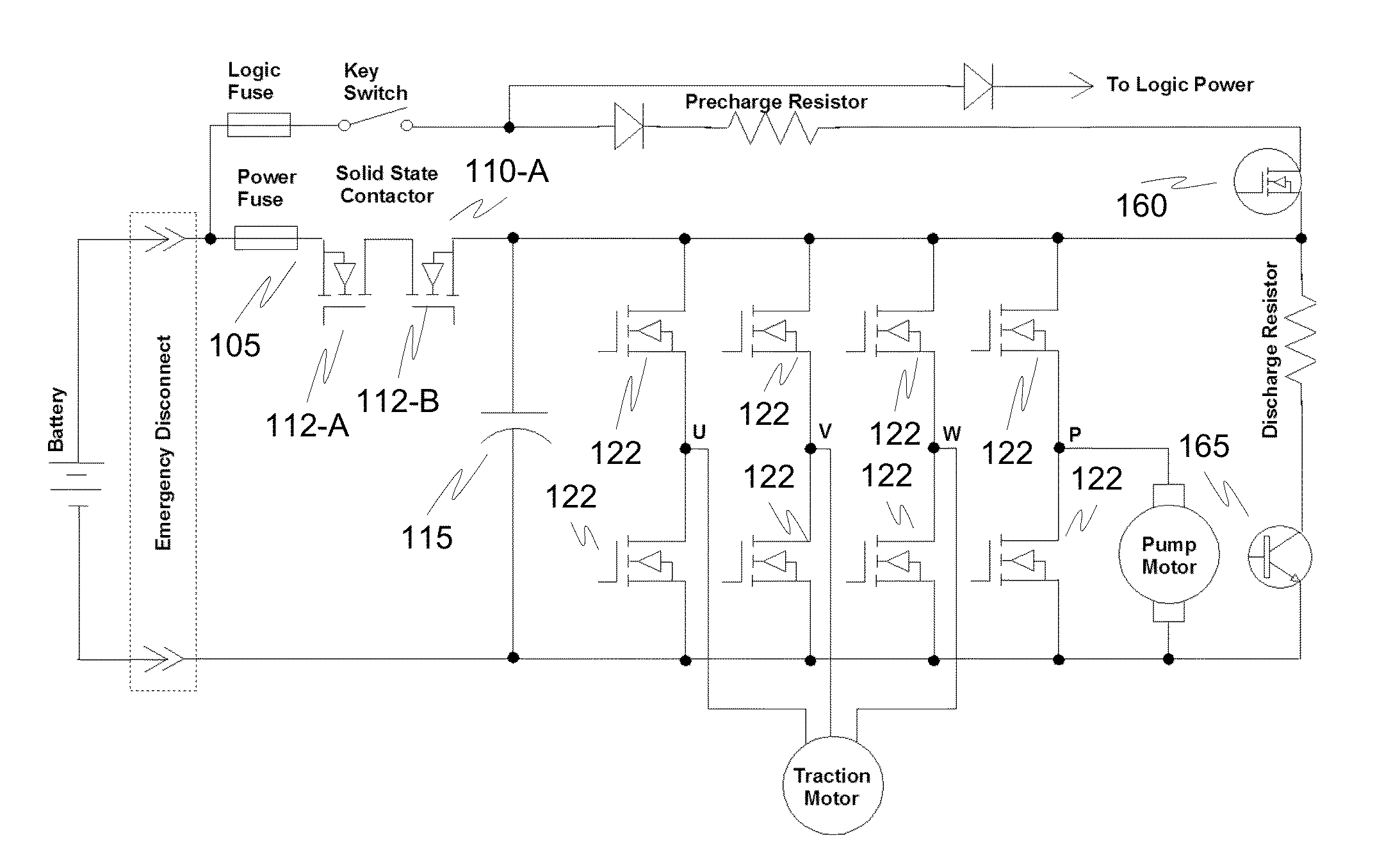
[0022]The present invention is generally directed to replacing discrete electromechanical main contactors in electrical vehicles, such as off-road battery powered electrical vehicles. Embodiments of the invention include solid-state solutions that address the safety concerns of battery powered electrical vehicles requiring comparatively high amperage (e.g., 40 A-800 A) and at a reasonable cost. Exemplary applications include material handling applications where a variety of safety guidelines are in place for battery powered electric vehicles.

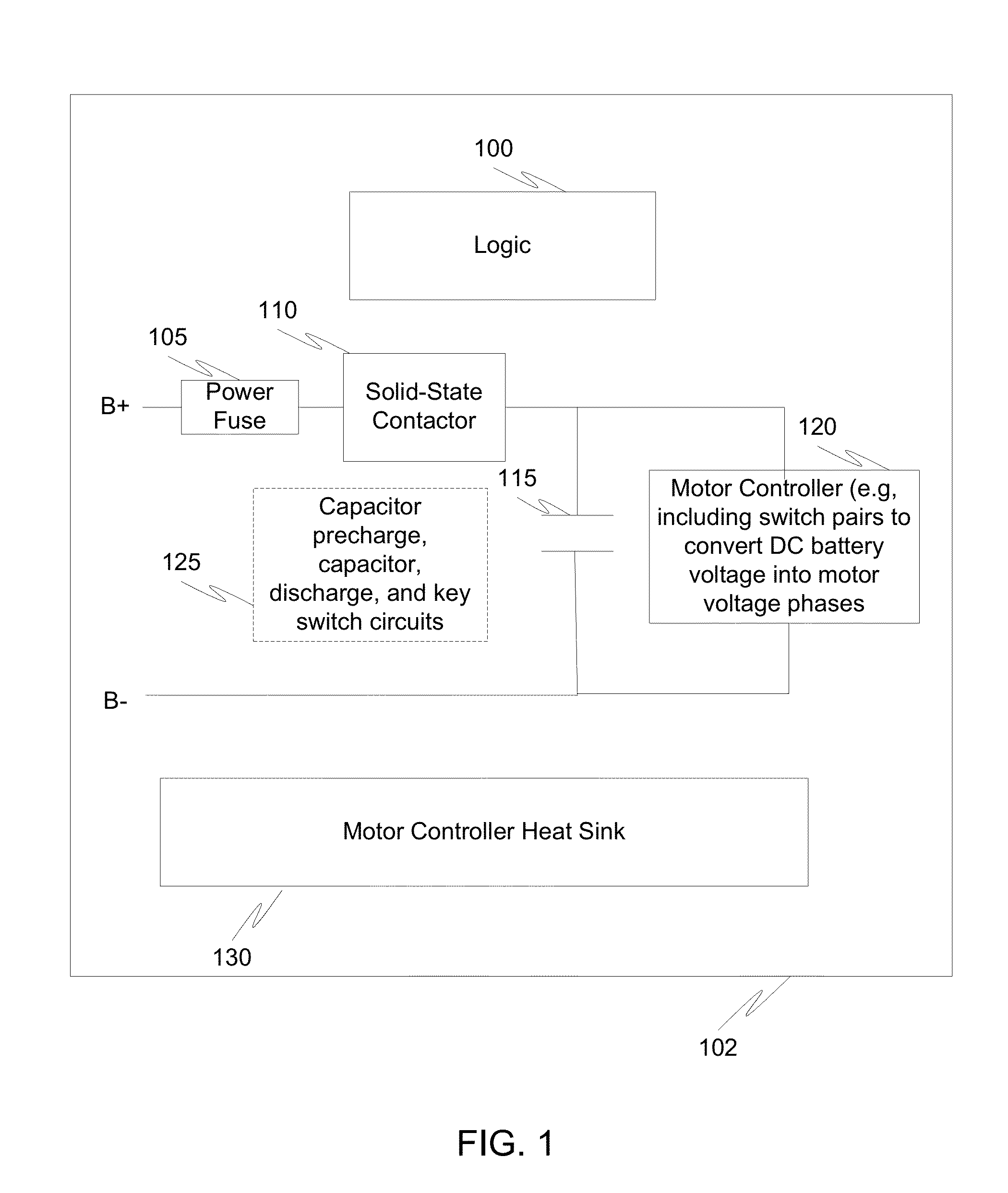
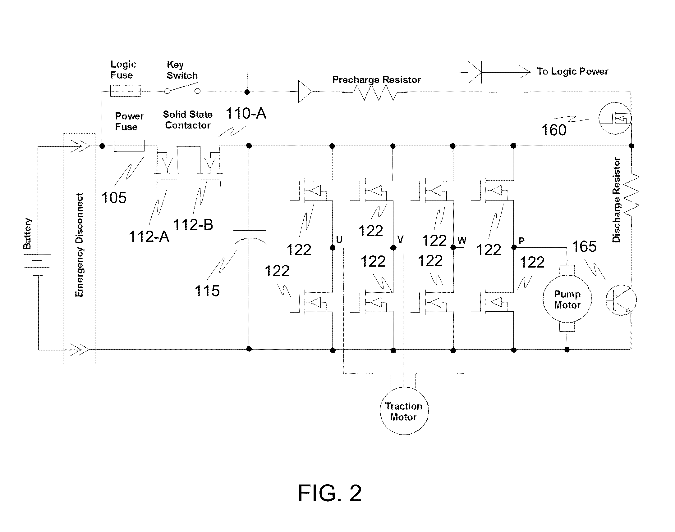
[0023]FIG. 1 is a high-level block diagram illustrating a solid-state contactor 110 integrated with other components in a system. Referring to FIG. 1, the present invention is generally directed to a solid-state contactor 110 inside of an enclosure 102 that houses other components such as a power fuse 105. Additionally, the solid state contactor may be integrated with a motor controller 120 having transistor switches (FETs) to convert a DC batte...


PUM


Abstract

Circuits, systems, and methods are disclosed to eliminate the requirement for an external electromechanical contactor. Integrating contactor circuits with a motor controller reduces cost. Additionally, the cost of the contactor circuit may be reduced by providing transistors designed to block current in only one direction in the event of an electrical fault corresponding to an electrical drive direction.

Description

FIELD OF THE INVENTION[0001]The present invention is related to contactors. More particularly, the present invention is directed to replacing electromechanical contactors with solid state circuits.BACKGROUND OF THE INVENTION[0002]Contactors are commonly used in many battery operated vehicles. Contactors are used to disconnect a system load from a battery. Main contactors used in high amperage battery-powered applications (e.g., 40 A to 800 A for 24-80V battery voltages) conventionally utilize electromechanical switch components due to a combination of considerations, including cost. In particular, electromechanical configurations lend themselves to handling high currents with reasonable component costs. An electromechanical contactor can either be sealed or unsealed, although sealed versions typically cost more.[0003]Main contactors are used in nearly all off highway electric vehicles that run on batteries. They are used primarily as a safety device to disconnect the motor controlle...

Claims


Application Information

Patent Timeline
IPC IPC(8): B60L3/04
CPCH02J7/0031H02P21/00H02P7/00
Inventor WHITE, ROGERPOST, STEPHEN
Owner CURTIS INSTRUMENTS INC
Learn More