Magnetic sensor and method for manufacturing magnetic sensor

a technology of magnetic sensor and manufacturing method, which is applied in the field of magnetic sensor, can solve the problems of limiting a measurement range and increasing offset, and achieve the effects of reducing the dispersion of the exchange coupling magnetic field, and reducing the dispersion of the magnetization direction

Inactive Publication Date: 2013-10-03
ALPS ALPINE CO LTD
View PDF0 Cites 10 Cited by
  • Summary
  • Abstract
  • Description
  • Claims
  • Application Information

AI Technical Summary

Benefits of technology

[0025]According to the method, unidirectional anisotropy can be imparted to the magnetization direction of the free magnetic layer in a direction different from the magnetization direction of the pinned magnetic layer without the antiferromagnetic layer being provided for pinning the magnetization of the pinned magnetic layer. Also, the heat treatment step is performed after magnetization of the permanent magnet layer, and thus heat treatment is performed under a condition in which a bias magnetic field is applied to the free magnetic layer from the permanent magnet layer. Consequently it is possible to suppress dispersion of the exchange coupling magnetic field applied to the free magnetic layer from the antiferromagnetic layer and to impart unidirectional anisotropy to the magnetization direction of the free magnetic layer by both the bias magnetic field from the permanent magnet layer and the exchange coupling magnetic field from the antiferromagnetic field.
[0026]According to the present invention, it is possible to provide a magnetic sensor capable of decreasing dispersion of the magnetization direction of a free magnetic layer in a magnetoresistive element and exhibiting high measurement accuracy over a wide range, and also provide a method for manufacturing a magnetic sensor.

Problems solved by technology

Therefore, a general magnetic sensor has the problem of limiting a measurement range because with a strong magnetic field to be measured, offset is increased even when the hard bias layer is provided.

Method used


Image

  • Magnetic sensor and method for manufacturing magnetic sensor
  • Magnetic sensor and method for manufacturing magnetic sensor
  • Magnetic sensor and method for manufacturing magnetic sensor

Examples


first embodiment

[0045](First Embodiment)

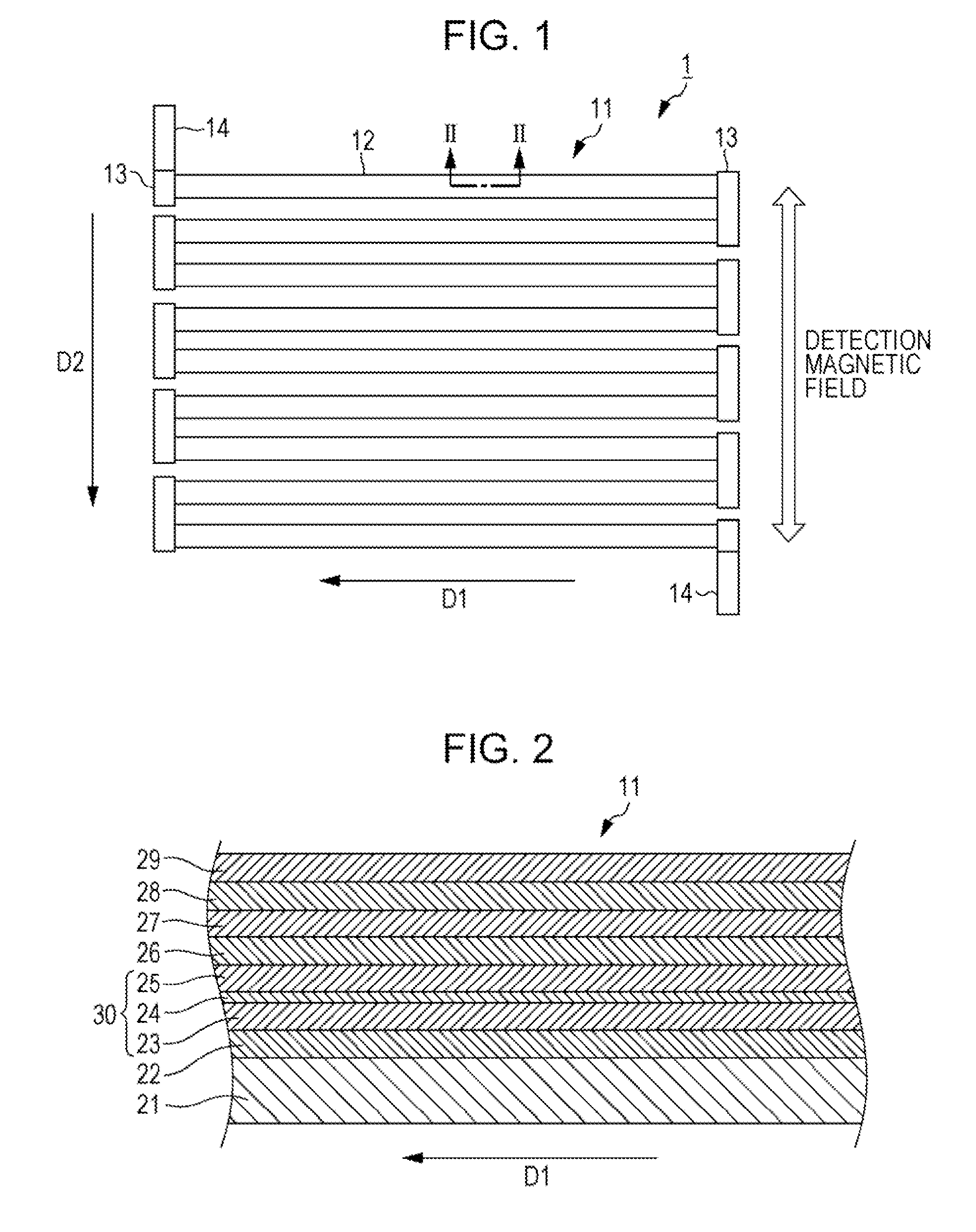
[0046]FIG. 1 is a schematic plan view showing an element structure of a magnetoresistive element 11 of a magnetic sensor 1 according to a first embodiment of the present invention. As shown in FIG. 1, the magnetic sensor 1 according to the embodiment has the stripe-shaped magnetoresistive element 11. The magnetoresistive element 11 has a folded shape (meandering shape) in which a plurality of stripe-shaped elongated patterns 12 (stripes) are arranged so that stripe longitudinal directions D1 (hereinafter simply referred to as “longitudinal direction D1”) are parallel to each other. In the meandering shape, a sensitivity axis direction (Pin direction) is a direction (stripe width direction D2) perpendicular to the longitudinal direction (stripe longitudinal direction D1) of the elongated patterns 12. In the meandering shape, a detection magnetic field and a cancel magnetic field are applied along the stripe width direction D2 perpendicular to the stripe longit...

second embodiment

[0096](Second Embodiment)

[0097]Next, an example of application of the magnetic sensor 1 according to the above-described embodiment is described. Although, in a description below, application of the magnetic sensor 1 according to the present invention to a magnetic balance-type current sensor is described, the magnetic sensor 1 according to the present invention is not limited to this and can be applied to other apparatuses.

[0098]FIG. 11 is a schematic perspective view of a magnetic balance-type current sensor 2 according to a second embodiment of the present invention, and FIG. 12 is a schematic plan view of the magnetic balance-type current sensor 2 according to the second embodiment.

[0099]As shown in FIGS. 11 and 12, the magnetic balance-type current sensor 2 according to the second embodiment is disposed near a conductor 101 in which a current 1 to be measured flows. The magnetic balance-type current sensor 2 includes a feedback circuit 102 which generates a magnetic field (canc...


PUM

PropertyMeasurementUnit
thicknessaaaaaaaaaa
thicknessaaaaaaaaaa
thicknessaaaaaaaaaa

Abstract

A magnetic sensor of the present invention includes a magnetoresistive element having a sensitivity axis in a specified direction, the magnetoresistive element having a laminated structure including a ferromagnetic pinned layer having a pinned magnetization direction, a nonmagnetic intermediate layer, a free magnetic layer having a magnetization direction varying with an external magnetic field, and an antiferromagnetic layer which applies an exchange coupling magnetic field to the free magnetic layer.

Description

CLAIM OF PRIORITY[0001]This application is a Continuation of International Application No. PCT / JP2011 / 077242 filed on Nov. 25, 2011, which claims benefit of Japanese Patent Application No. 2010-280498 filed on Dec. 16, 2010. The entire contents of each application noted above are hereby incorporated by reference.BACKGROUND OF THE INVENTION[0002]1. Field of the Invention[0003]The present invention relates to a magnetic sensor using a magnetoresistive element (TMR element, GMR element) and a method for manufacturing a magnetic sensor.[0004]2. Description of the Related Art[0005]In the field of motor driving technology for electric cars and hybrid cars, current sensors capable of non-contact measurement of large currents are generally required because relatively large currents are handled. Those known as the current sensors use magnetic sensors that detect an induced magnetic field from a current to be measured. Examples of magnetic detecting elements for magnetic sensors include magne...

Claims


Application Information

Patent Timeline
Patent Type & Authority Applications(United States)
IPC IPC(8): G01R33/09
CPCB82Y25/00G01R33/093H01L43/08B82Y40/00H01F41/305G01R15/205H01F10/3268H10N50/10
Inventor KOIKE, FUMIHITOASATSUMA, KOTASAITO, MASAMICHITAKAHASHI, AKIRAIDE, YOSUKE
Owner ALPS ALPINE CO LTD
Why Eureka
Try Eureka