Medical device which acquires the picture for observation

a medical device and picture technology, applied in the field of medical devices, can solve the problems of complex configuration and difficult to make the tip end smaller, and achieve the effect of reducing the size of the insertion unit and suppressing the energy consumed by illumination

Active Publication Date: 2013-10-03
OLYMPUS CORP
View PDF2 Cites 8 Cited by
  • Summary
  • Abstract
  • Description
  • Claims
  • Application Information

AI Technical Summary

Benefits of technology

[0011]An embodiment according to the invention relates to a medical instrument mounting an imaging apparatus which moves a field of view, includes an illumination apparatus which selectively illuminates a range of a field of view, suppresses energy consumed by illumination, and achieves downsizing of an insertion unit.

Problems solved by technology

When applied to an endoscope in which a solid-state image sensing device, such as a CCD, is used as an imaging apparatus, a movement mechanism which makes the imaging apparatus movable together with an illumination unit has a complex configuration, and a tip end is not easy to make smaller.

Method used


Image

  • Medical device which acquires the picture for observation
  • Medical device which acquires the picture for observation
  • Medical device which acquires the picture for observation

Examples


first embodiment

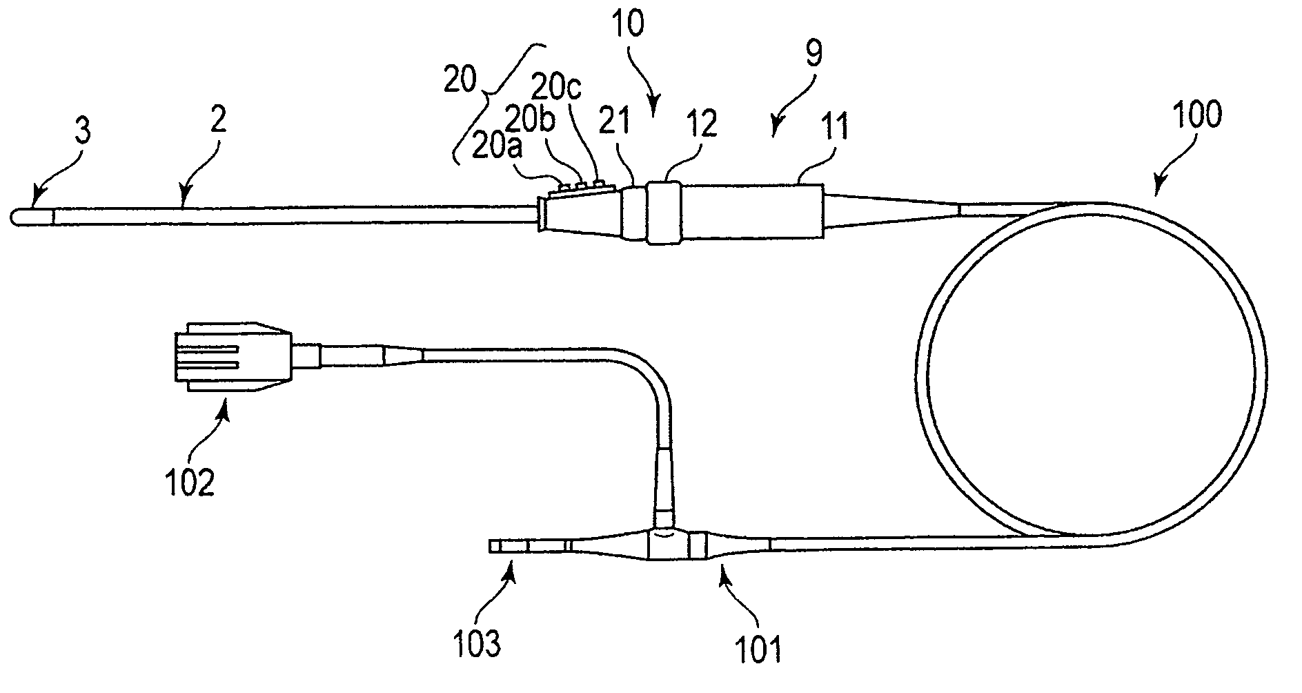
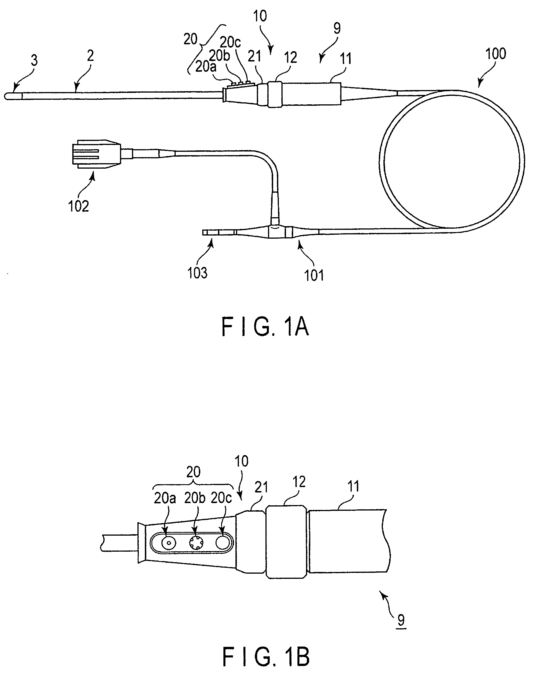
[0044]FIG. 1A shows an exterior configuration of an endoscope apparatus as an embodiment according to a medical device of the invention. FIG. 1B shows an exterior configuration of an operation section 9 of the endoscope apparatus.

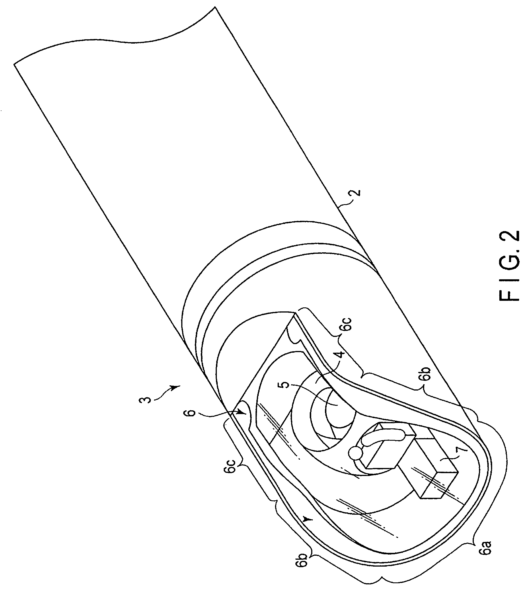
[0045]FIG. 2 is a perspective view showing an exterior configuration of a tip end mechanism of an insertion section in a body of an endoscope apparatus.

[0046]The present embodiment describes, as an example, the configuration of a tip end provided on a rigid insertion section in a rigid endoscope. The illumination section of the present embodiment has an illumination range of illumination light which covers a whole field of view (or the all field of view to image) to observe, and illuminates a partial illumination area with illumination light, targeting a current field of view, in synchronism with pivoting of an observation section (or an imaging section). In each of embodiments and modifications described below, the observation section will be described as ...

second embodiment

[0097]Next, an illumination-light switching mechanism according to the second embodiment will be described with reference to FIGS. 13A, 13B, and 13C.

[0098]A field-of-view switching mechanism of the present embodiment is configured to divisionally shield light flux introduced from a light source by using a liquid crystal shutter, and to illuminate only illumination light which illuminates a current field of view to image by an imaging section, from an illumination window.

[0099]FIG. 13A conceptually shows an example configuration of the illumination-light switching mechanism provided at a tip end of the insertion section of a rigid endoscope. FIG. 13B shows a light inlet surface on the side of the insertion section.

[0100]FIG. 13C shows a light outlet surface which includes a liquid-crystal shutter. The field-of-view switching mechanism which pivots the imaging section to move the field of view is equivalent to that of the first embodiment described above, and will be denoted at the co...

third embodiment

[0107]Next, an illumination-light switching mechanism according to the third embodiment will be described with reference to FIGS. 14, 15A, and 15B. A field-of-view switching mechanism of the present embodiment is configured to allow light flux introduced from a light source to divisionally penetrate by using cutout windows, and to illuminate only illumination light which illuminates a current field of view of an imaging section from an illumination window.

[0108]FIG. 14 shows an exterior configuration of the illumination-light switching mechanism provided at a tip end of the insertion section of a rigid endoscope. FIG. 15A shows a light inlet surface on the side of the insertion section. FIG. 15B shows a light outlet surface which includes a mechanical shutter plate. The field-of-view switching mechanism which pivots an imaging section to move a field of view is equivalent to that of the first embodiment described above, and will be denoted at the common reference signs. Descriptions...


PUM


Abstract

In a medical device, a field-of-view switching mechanism which moves a field of view imaged by an observation section, and an illumination-light switching mechanism including an illumination section having an illumination range of illumination light whose entire field of view is covered by movement, are configured integrally with each other. The illumination light is illuminated to the current field of view by moving the illumination range of the illumination light, in synchronism with pivoting of an observation and in compliance with the field of view.

Description

CROSS-REFERENCE TO RELATED APPLICATIONS[0001]This is a Continuation Application of PCT Application No. PCT / JP2012 / 066001, filed Jun. 22, 2012, which was published under PCT Article 21(2) in Japanese.[0002]This application is based upon and claims the benefit of priority from prior the Japanese Patent Application No. 2011-175163, filed Aug. 10, 2011 the entire contents of which are incorporated here by references.BACKGROUND OF THE INVENTION[0003]1. Field of the Invention[0004]The invention relates to a medical device which illuminates in accordance with moving of a field of view, and obtains image information of an object to observe.[0005]2. Description of the Related Art[0006]At a tip end of a body of an endoscope as a medical devicemedical device, there are provided an imaging apparatus which obtains a video image as image information by imaging an object to observe, and an illumination unit which illuminates the object for imaging. The imaging apparatus does not need movement of t...

Claims


Application Information

Patent Timeline
Patent Type & Authority Applications(United States)
IPC IPC(8): G02B23/24
CPCG02B23/24A61B1/00183G02B23/2461G02B23/2423A61B1/0607A61B1/0623A61B1/07A61B1/00042A61B1/0605A61B1/0625A61B1/0627
Inventor AKUI, NOBUAKITAKEKOSHI, SATOSHI
Owner OLYMPUS CORP
Why Eureka
Try Eureka