
Magnet Array Configuration for Higher Efficiency Planar Motor

a planar motor and magnet array technology, applied in the field of semiconductor processing equipment, can solve the problems of adversely affecting affecting the quality of the wafer processed by the exposure stage system, and compromising the precision and efficiency of the stage system, so as to reduce the amount of heat associated with x coils, reduce the weight of the stage, and minimize power consumption. the effect of heat outpu

Inactive Publication Date: 2013-10-03
NIKON CORP
View PDF4 Cites 11 Cited by
  • Summary
  • Abstract
  • Description
  • Claims
  • Application Information

AI Technical Summary

Benefits of technology

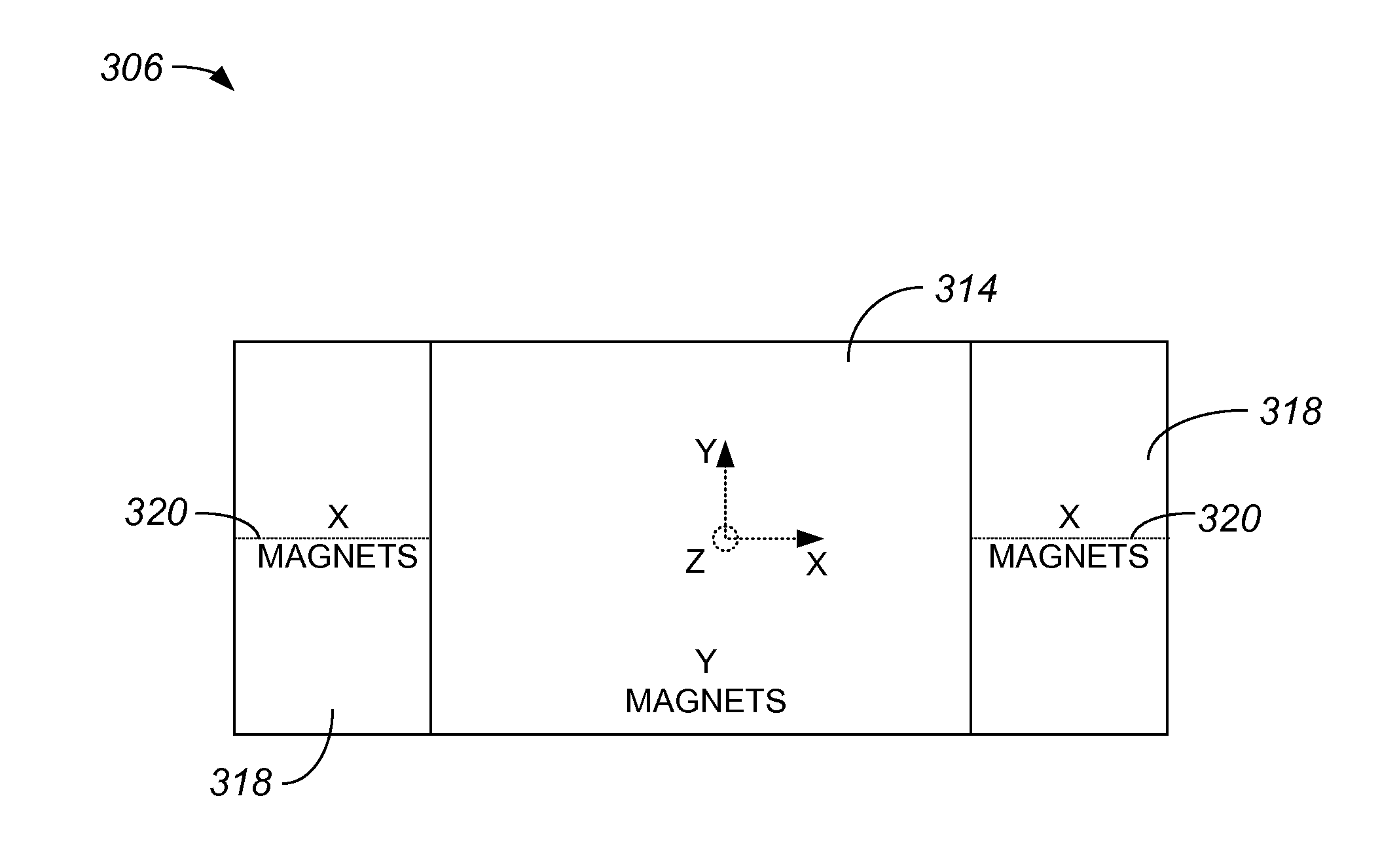
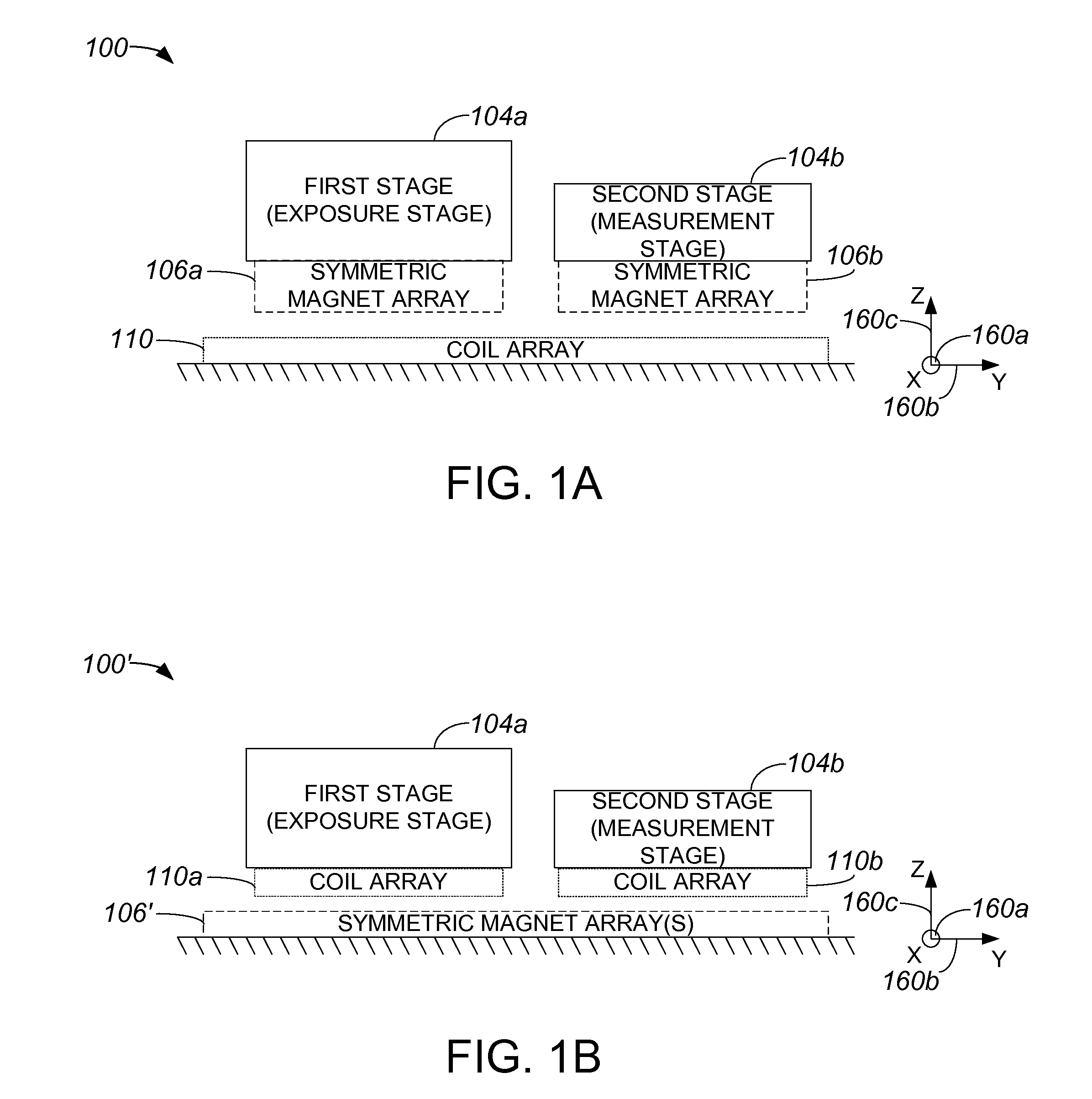
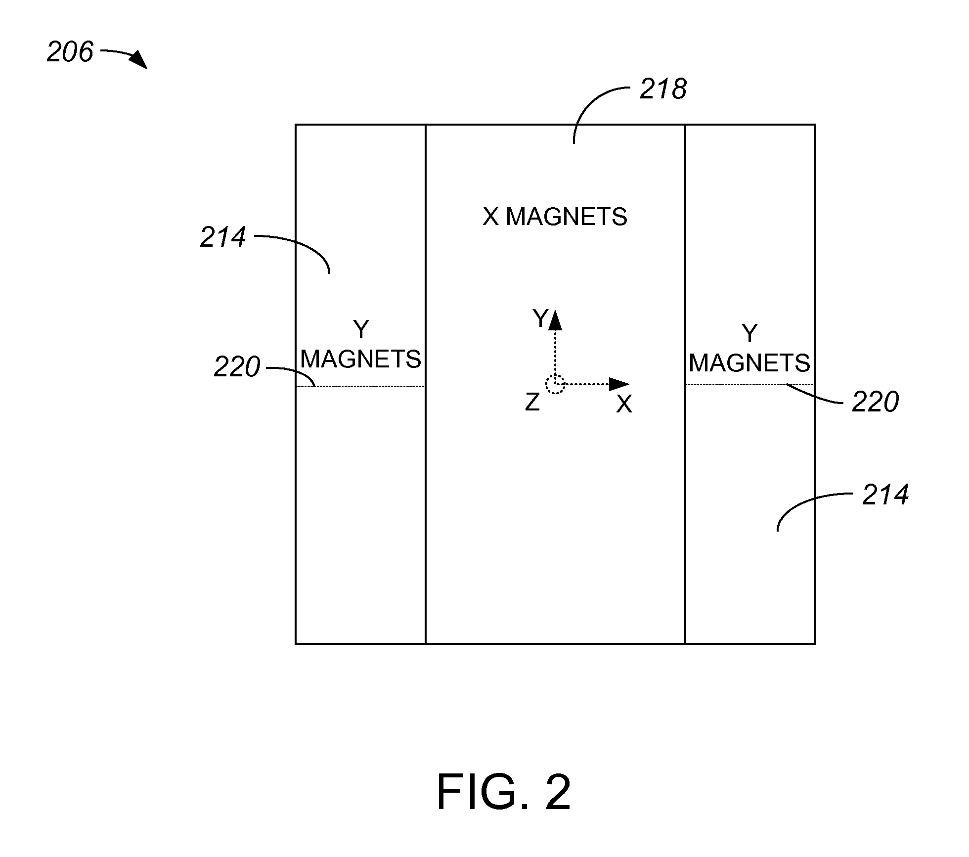
The present invention is about a stage that uses Y actuators for levitation, pitch compensation, and roll compensation while avoiding the use of X actuators. By using Y magnets and Y coils for acceleration and pitch / roll compensation, the amount of heat generated by X coils is reduced. The stage can be used for exposure or measurement purposes. The technical effects of the invention are minimized power consumption and heat output from coils while maintaining sufficient force in all directions.

Problems solved by technology

The precision and efficiency with which a stage system such as an exposure stage system operates may be compromised due to relatively large amounts of heat generated by actuators.
When relatively large amounts of heat compromise the operation of an exposure stage system, the quality of wafers processed by the exposure stage system may be adversely affected.
Further, the mass of X magnets and Y magnets of an overall magnet array that is part of an actuator arranged to drive a stage in a stage system may also adversely affect the precision and efficiency of the stage system.
A heavier stage system is generally more difficult to activate, may have less favorable vibration characteristics, and typically has higher power requirements than a lighter stage system.

Method used


Image

  • Magnet Array Configuration for Higher Efficiency Planar Motor
  • Magnet Array Configuration for Higher Efficiency Planar Motor
  • Magnet Array Configuration for Higher Efficiency Planar Motor

Examples


Embodiment Construction

[0033]Example embodiments of the present invention are discussed below with reference to the various figures. However, those skilled in the art will readily appreciate that the detailed description given herein with respect to these figures is for explanatory purposes, as the invention extends beyond these embodiments.

[0034]High heat generated by coils of planar motors, e.g., planar motors that have quadrant based magnet arrays which contain X magnets and Y magnets, used to drive a stage of a stage system often has an adverse effect on the performance of the stage system. For example, heat generated by coils may deform structures due to a thermal load, and / or heat generated by coils may change a refractive index of air surrounding a stage by changing a temperature which, in turn, may affect the accuracy of stage position measurement systems such as interferometers, encoders, etc. As such, reducing the amount of heat generated by coils of a planar motor that drives a stage of a stage...


PUM


Abstract

According to one aspect, a stage apparatus includes a first surface, a second surface, an overall magnet array, and a plurality of coils. The overall magnet array is mounted on the first surface, and includes an X magnet array and a Y magnet array. The coils are mounted on the second surface, and include a first coil that cooperates with the X magnet array to control force on the first surface along an x-axis. The coils also include a second coil that cooperates with the Y magnet array to control force on the first surface along a y-axis. The second coil cooperates with the overall magnet array to control force applied to the first surface in a direction normal to the first surface. The first coil does not cooperate with the overall magnet array to control the force applied in the direction normal to the first surface.

Description

CROSS REFERENCE TO RELATED APPLICATION[0001]The present application claims benefit under 35 U.S.C. §119(e) of U.S. Provisional Patent Application No. 61 / 599,572, entitled “Magnet Array Configuration for Higher Efficiency Planar Motor,” filed Feb. 16, 2012, which is incorporated herein by reference in its entirety.BACKGROUND OF THE INVENTION[0002]1. Field of the Invention[0003]The present invention relates generally to equipment used in semiconductor processing. More particularly, the present invention relates to increasing the efficiency of an overall stage apparatus that includes a planar motor by utilizing a magnet array that is symmetric with respect to an x-axis and a y-axis such that either Y magnets may be used substantially alone or X magnets may be used substantially alone to provide for levitation relative to a z-axis, as well as to provide pitch compensation, and / or roll compensation.[0004]2. Description of the Related Art[0005]The precision and efficiency with which a sta...

Claims


Application Information

Patent Timeline
IPC IPC(8): G03F7/20H02K41/03
CPCG03F7/70716G03F7/70758H02K2201/18H02K41/031
Inventor MAHADESWARASWAMY, CHETANBINNARD, MICHAEL B.MORIMOTO, SHIGERU
Owner NIKON CORP
Learn More