Optical fiber manufacturing method, optical fiber and endoscope

Active Publication Date: 2013-10-03
OLYMPUS CORP
View PDF0 Cites 4 Cited by
  • Summary
  • Abstract
  • Description
  • Claims
  • Application Information

AI Technical Summary

Problems solved by technology

However, while optical fibers for optical communications each convey light with a predetermined narrow range of wavelengths over a long distance of several kilometers or more, optical fibers for endoscopes need to guide a large amount of light with a broad range of wavelengths, i.e., visible light, although the optical fibers for endoscopes guide such large amount of light over only a short distance of several meters.

Method used


Image

  • Optical fiber manufacturing method, optical fiber and endoscope
  • Optical fiber manufacturing method, optical fiber and endoscope
  • Optical fiber manufacturing method, optical fiber and endoscope

Examples


Embodiment Construction

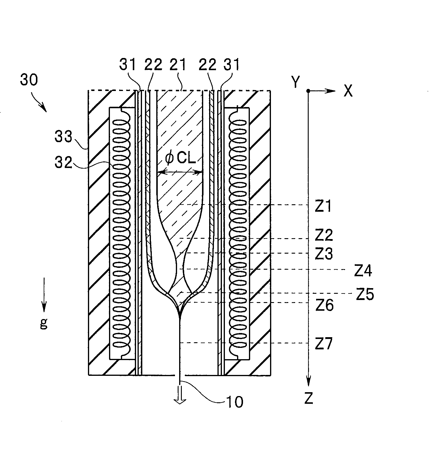
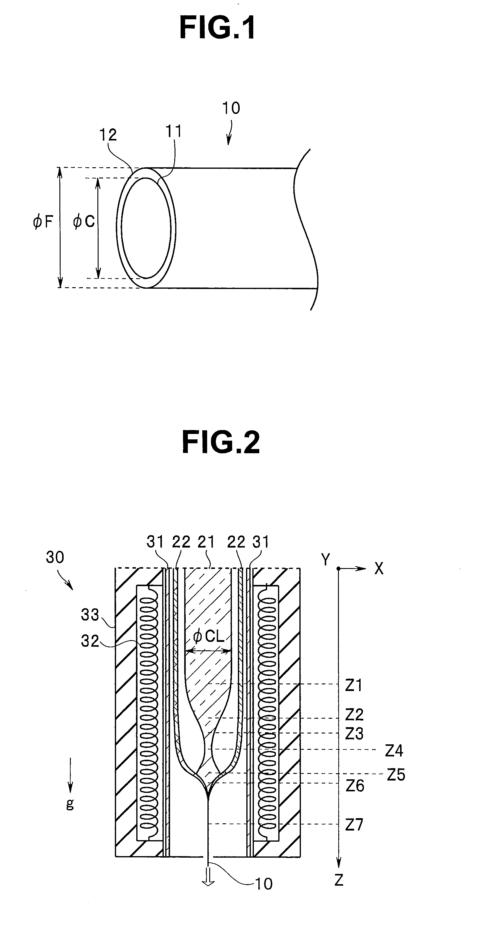
[0018]As illustrated in FIG. 2, an optical fiber 10 according to an embodiment is obtained as a result of a vertically held, elongated core rod 21 including a core glass inserted into a center of a hollow portion of a vertically-held, elongated clad tube 22 including a clad glass being heated and subjected to “fiber drawing” under downward tension in an inner portion of an upright fiber drawing furnace 30.

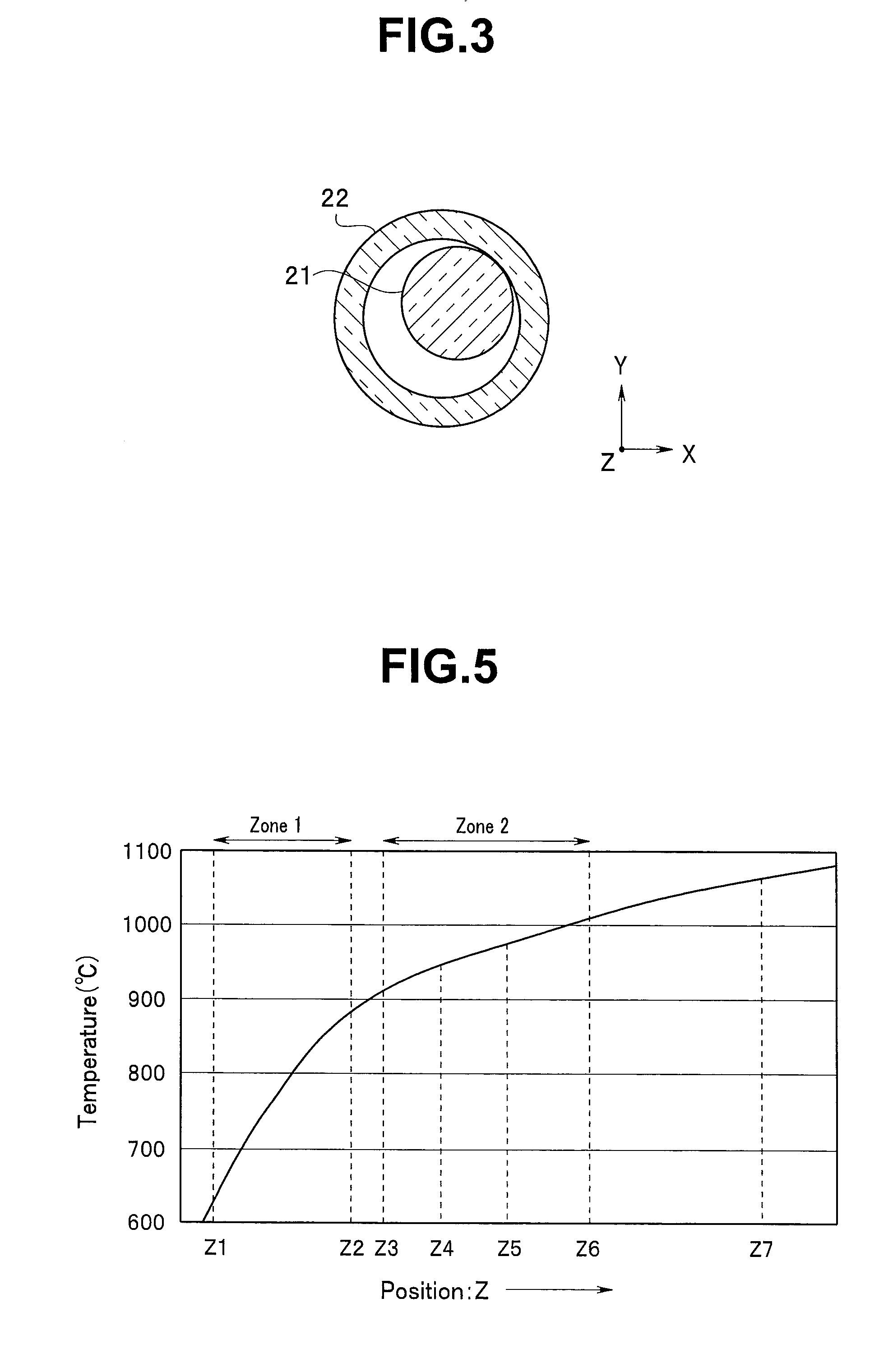
[0019]In the fiber drawing furnace 30, a heater 32 and a heat-insulating material 33 are disposed so as to surround a central furnace tube 31, which provides a heating space. An inner portion of the furnace tube 31 is designed so that the temperature increases toward the lower side from the upper side.

[0020]Hereinafter, as illustrated in FIG. 2, positions Z in the inner portion of the fiber drawing furnace 30 are indicated by values in a Z-axis coordinate in which an upper portion of the fiber drawing furnace 30 is an origin thereof and a Z-axis is an axis with its value increasing...


PUM

PropertyMeasurementUnit
core diameteraaaaaaaaaa
diameter φCaaaaaaaaaa

Abstract

Provided is a method for manufacturing an optical fiber that is inserted into an insertion portion of an endoscope and guides light, wherein inside an upright fiber drawing furnace, inside a hollow clad tube including a clad glass having a viscosity η1 of 5.0<Log η1<7.0 at a temperature at which a viscosity η2 of a core glass becomes Log η2=3.5, the core glass in a fluidized state runs down by gravity, whereby the core glass and the clad glass are integrated.

Description

CROSS REFERENCE TO RELATED APPLICATION[0001]This application is a continuation application of PCT / JP2012 / 081973 filed on Dec. 10, 2012 and claims benefit of Japanese Application No. 2011-277355 filed in Japan on Dec. 19, 2011, the entire contents of which are incorporated herein by this reference.BACKGROUND OF THE INVENTION[0002]1. Field of the Invention[0003]Embodiments of the present invention relate to a method for manufacturing an optical fiber that is inserted into an insertion portion of an endoscope and guides light, the optical fiber, and an endoscope including the optical fiber.[0004]2. Description of the Related Art[0005]Medical endoscopes need to illuminate an object in order to observe the inside of a dark body cavity. Therefore, a light guide is used to guide light generated by a light source apparatus to an illumination portion disposed in a distal end portion of an insertion portion of the respective endoscopes.[0006]A light guide has a configuration in which numerous...

Claims


Application Information

Patent Timeline
Patent Type & Authority Applications(United States)
IPC IPC(8): A61B1/00G02B6/06C03B37/027
CPCC03B37/02718C03B2205/16A61B1/00G02B23/2469A61B1/0011A61B1/0017A61B1/07C03B37/02754C03B37/029C03B2201/10C03B2201/32C03B2201/50C03B2203/222C03B2203/32C03B2205/63C03B2205/14G02B6/06Y02P40/57
Inventor TANABE, MAKOTOTAKAGI, HIROKI
Owner OLYMPUS CORP
Why Eureka
Try Eureka