
Fuel cell reforming system with carbon dioxide removal

a fuel cell and carbon dioxide technology, applied in the field of fuel cell carbon dioxide (co2) removal systems, can solve the problems of affecting the operation of fuel cells and combustion engines, reforming may occur, etc., and achieve the effect of increasing the amount of co2 generated

Active Publication Date: 2013-10-03
CUMMINS ENTERPRISE LLC
View PDF4 Cites 32 Cited by
  • Summary
  • Abstract
  • Description
  • Claims
  • Application Information

AI Technical Summary

Benefits of technology

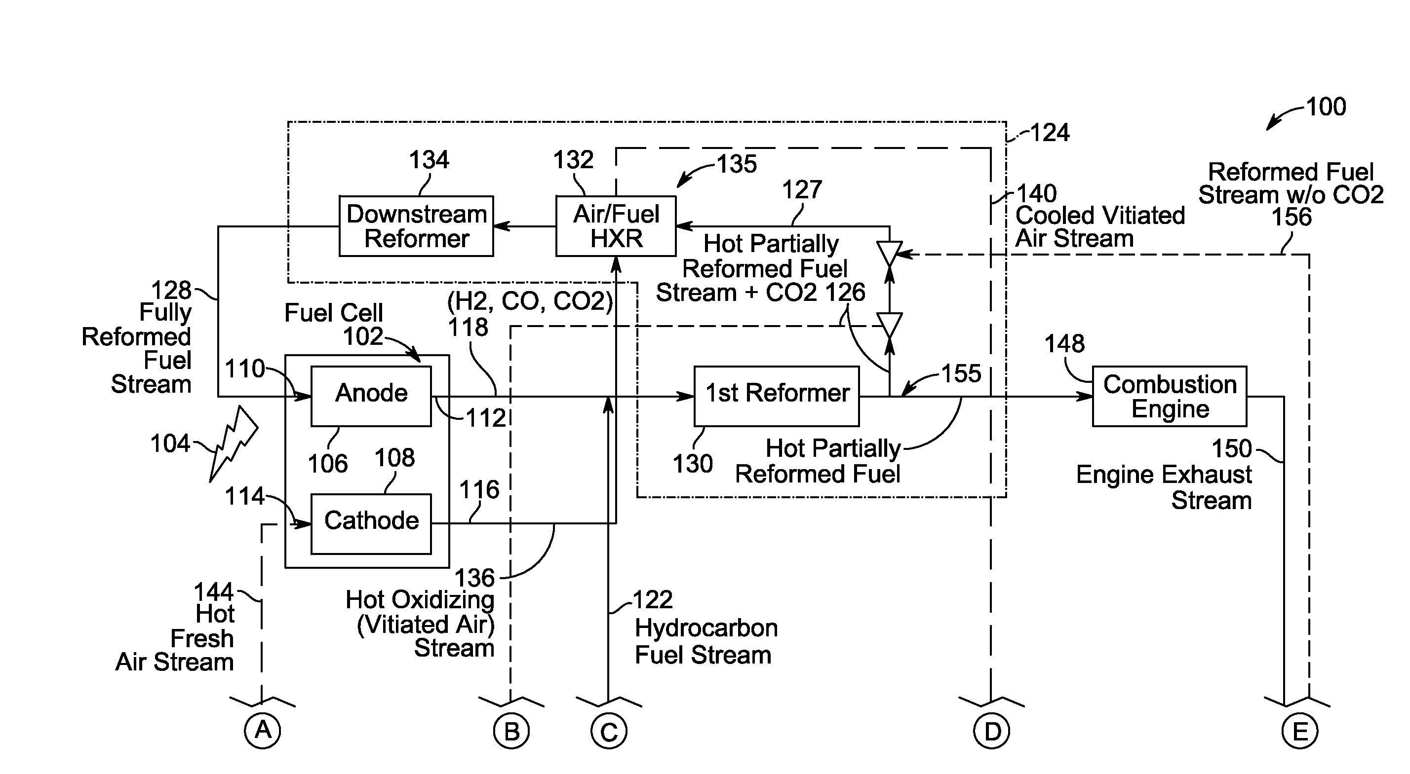
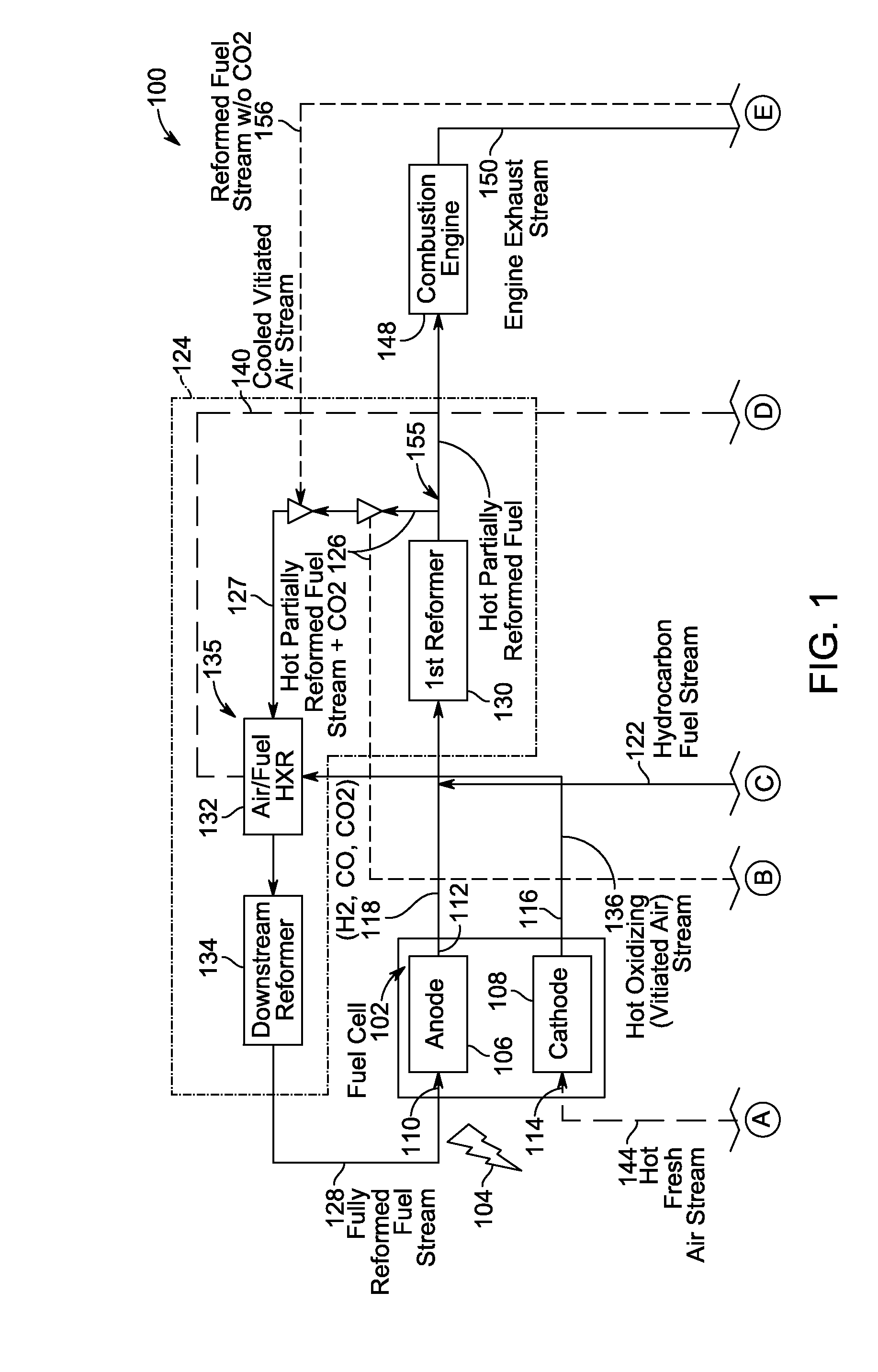
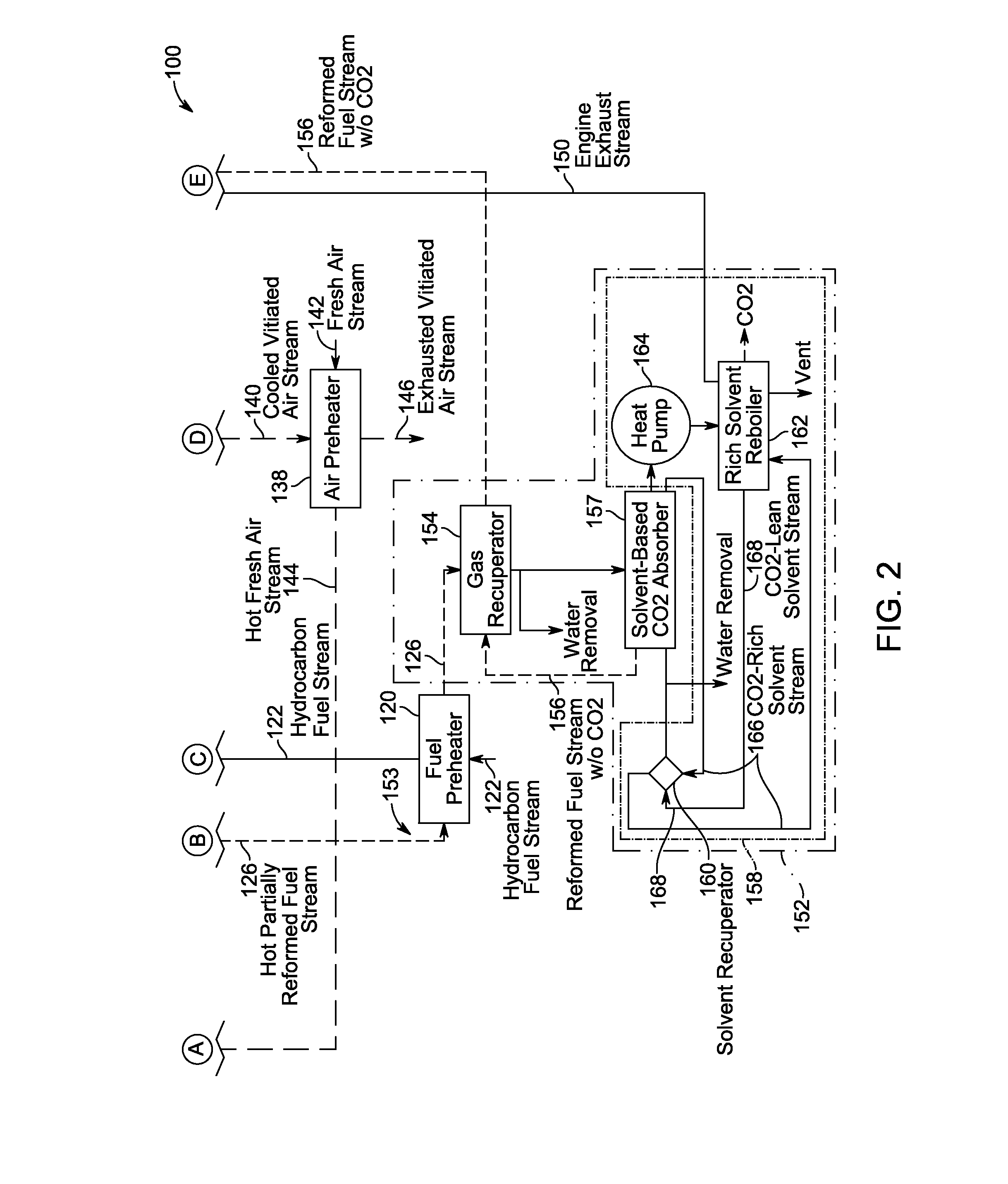
This patent describes a power generation system that uses a fuel cell to generate electricity. The system includes a fuel cell that produces a tail gas containing carbon dioxide. The system also includes a hydrocarbon fuel reforming system that mixes the hydrocarbon fuel with the fuel cell tail gas to create a reformed fuel stream with carbon dioxide. The system splits the reformed fuel stream into two parts, with one part being sent back to the fuel cell and the other being sent to a CO2 removal system. The CO2 removal system uses a solvent-based absorber to capture the carbon dioxide, and a regeneration system to regenerate the absorber for continued use. The technical effects of this patent include an improved carbon dioxide removal system that reduces emissions from power generation systems and a more efficient fuel cell that produces less tail gas.

Problems solved by technology

Moreover, such reforming may occur internal and / or external to the fuel cell.
However, some known combined cycle systems that include fuel cells facilitate energy losses in the form of heat losses such that fuel cells routinely achieve a conversion efficiency that is only about 50%.
Excess CO2 in the reformed fuel stream may adversely affect operation of the fuel cells and combustion engines.

Method used


Image

  • Fuel cell reforming system with carbon dioxide removal
  • Fuel cell reforming system with carbon dioxide removal
  • Fuel cell reforming system with carbon dioxide removal

Examples


Embodiment Construction

[0018]In the following specification and the claims, reference will be made to a number of terms, which shall be defined to have the following meanings.

[0019]The singular forms “a”, “an”, and “the” include plural references unless the context clearly dictates otherwise.

[0020]“Optional” or “optionally” means that the subsequently described event or circumstance may or may not occur, and that the description includes instances where the event occurs and instances where it does not.

[0021]Approximating language, as used herein throughout the specification and claims, may be applied to modify any quantitative representation that could permissibly vary without resulting in a change in the basic function to which it is related. Accordingly, a value modified by a term or terms, such as “about” and “substantially”, are not to be limited to the precise value specified. In at least some instances, the approximating language may correspond to the precision of an instrument for measuring the val...


PUM

PropertyMeasurementUnit
electric poweraaaaaaaaaa
concentrationaaaaaaaaaa
heataaaaaaaaaa

Abstract

A power generation system includes a fuel cell including an anode that generates a tail gas. The system also includes a hydrocarbon fuel reforming system that mixes a hydrocarbon fuel with the fuel cell tail gas and to convert the hydrocarbon fuel and fuel tail gas into a reformed fuel stream including CO2. The reforming system further splits the reformed fuel stream into a first portion and a second portion. The system further includes a CO2 removal system coupled in flow communication with the reforming system. The system also includes a first reformed fuel path coupled to the reforming system. The first path channels the first portion of the reformed fuel stream to an anode inlet. The system further includes a second reformed fuel path coupled to the reforming system. The second path channels the second portion of the reformed fuel stream to the CO2 removal system.

Description

CROSS REFERENCE TO RELATED APPLICATIONS[0001]This application is a continuation-in-part of U.S. patent application Ser. No. 13 / 077,066, filed on Mar. 31, 2011, entitled “Solid-Oxide Fuel Cell High-Efficiency Reform-and-Recirculate System,” which is incorporated by reference herein in its entirety.BACKGROUND[0002]The field of the disclosure relates generally to combined cycle fuel cell systems and, more particularly, to fuel cell carbon dioxide (CO2) removal systems and methods of operation thereof.[0003]Fuel cells are electrochemical energy conversion devices that have demonstrated a potential for relatively high efficiency and low pollution in power generation. A fuel cell generally provides a direct current (DC) which may be converted to alternating current (AC) through, e.g., an inverter. The DC or AC voltage can be used to power motors, lights, and any number of electrical devices and systems. Fuel cells may operate in stationary, semi-stationary, or portable applications.[0004]...

Claims


Application Information

Patent Timeline
Patent Type & Authority Applications(United States)
IPC IPC(8): H01M8/06
CPCY02E60/50Y02B90/12Y02E60/525Y02E60/56Y02E60/563H01M8/0612H01M8/0668H01M8/04007H01M2008/1293H01M2250/40H01M2250/402H01M2250/407H01M8/0662Y02B90/10Y02P90/40
Inventor SHAPIRO, ANDREW PHILIPPERRY, ROBERT JAMESALINGER, MATTHEW JOSEPHBIEDERMAN, BRUCE PHILIPHUSSAINI, IRFAN SAIFSPIRY, IRINA
Owner CUMMINS ENTERPRISE LLC
Learn More