Image processing apparatus and method thereof
a technology of image processing and processing apparatus, which is applied in the field of image processing apparatus, can solve the problems of affecting visual performance, eye sight getting worse, and difficulty in quick acquisition of image by td-o
- Summary
- Abstract
- Description
- Claims
- Application Information
AI Technical Summary
Benefits of technology
Problems solved by technology
Method used
Image
Examples
first embodiment
Orientation (Parallelness)
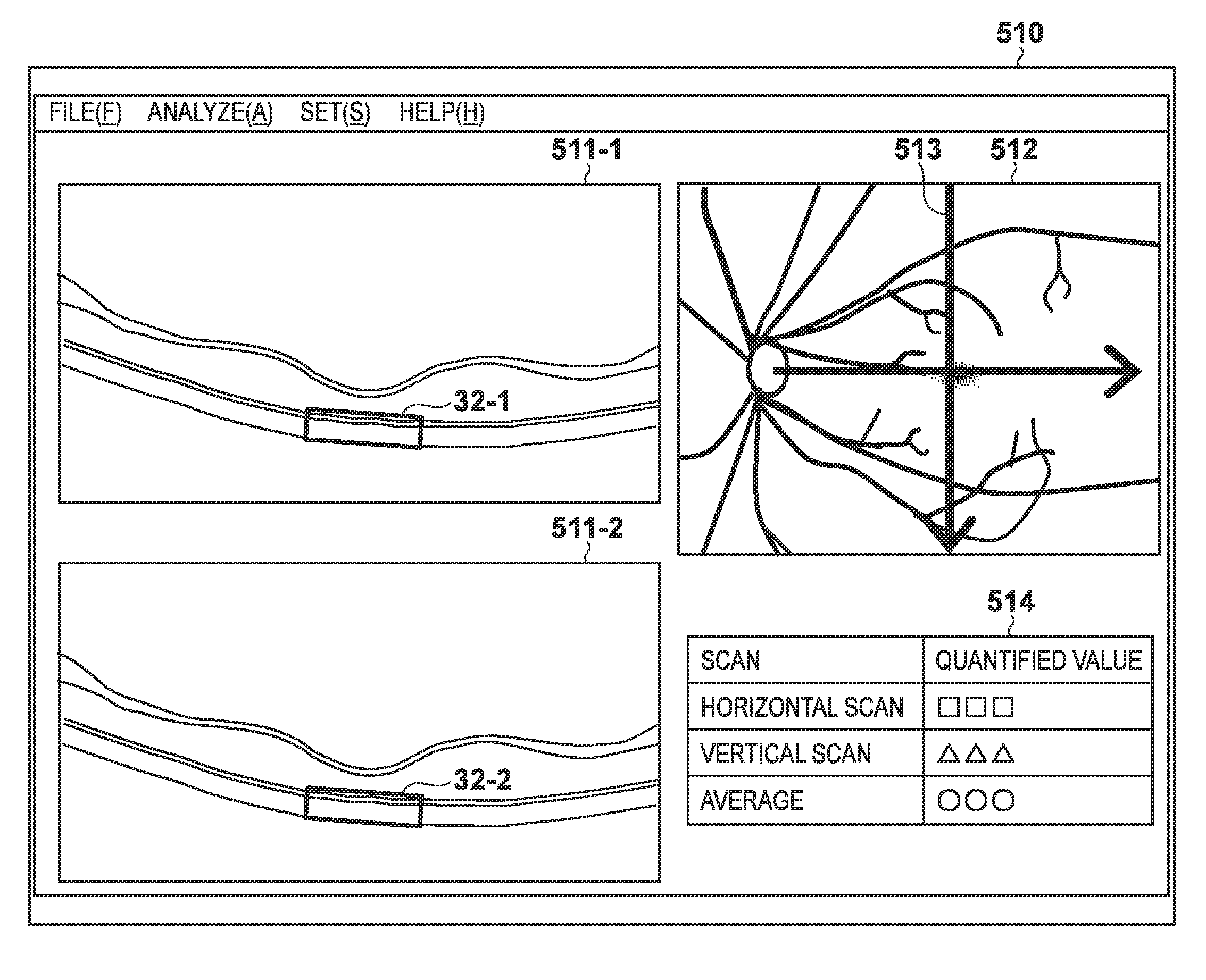
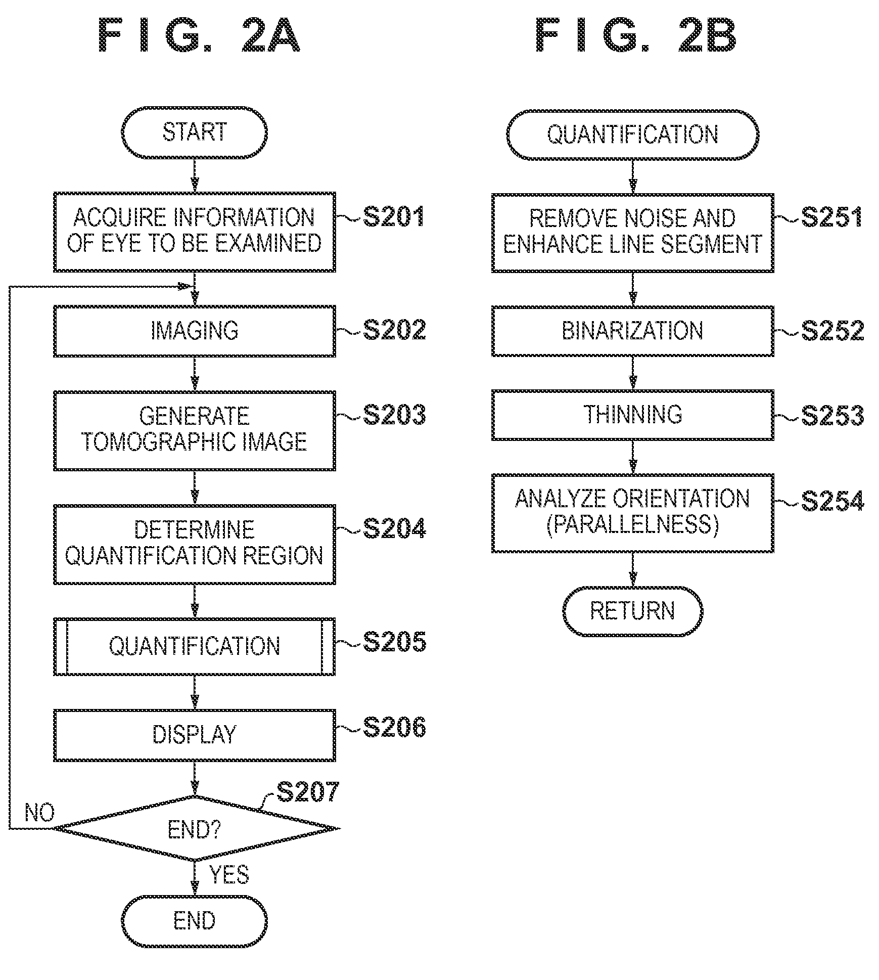
[0034]The first embodiment of the present invention will be described below with reference to the accompanying drawings. Note that an image processing system including an image processing apparatus according to this embodiment quantifies the degree of distortion in the layer structure of a retina. In particular, the image processing system quantifies the degree of distortion in a photoreceptor layer near the fovea. Details of the image processing system including the image processing apparatus according to this embodiment will be described below.
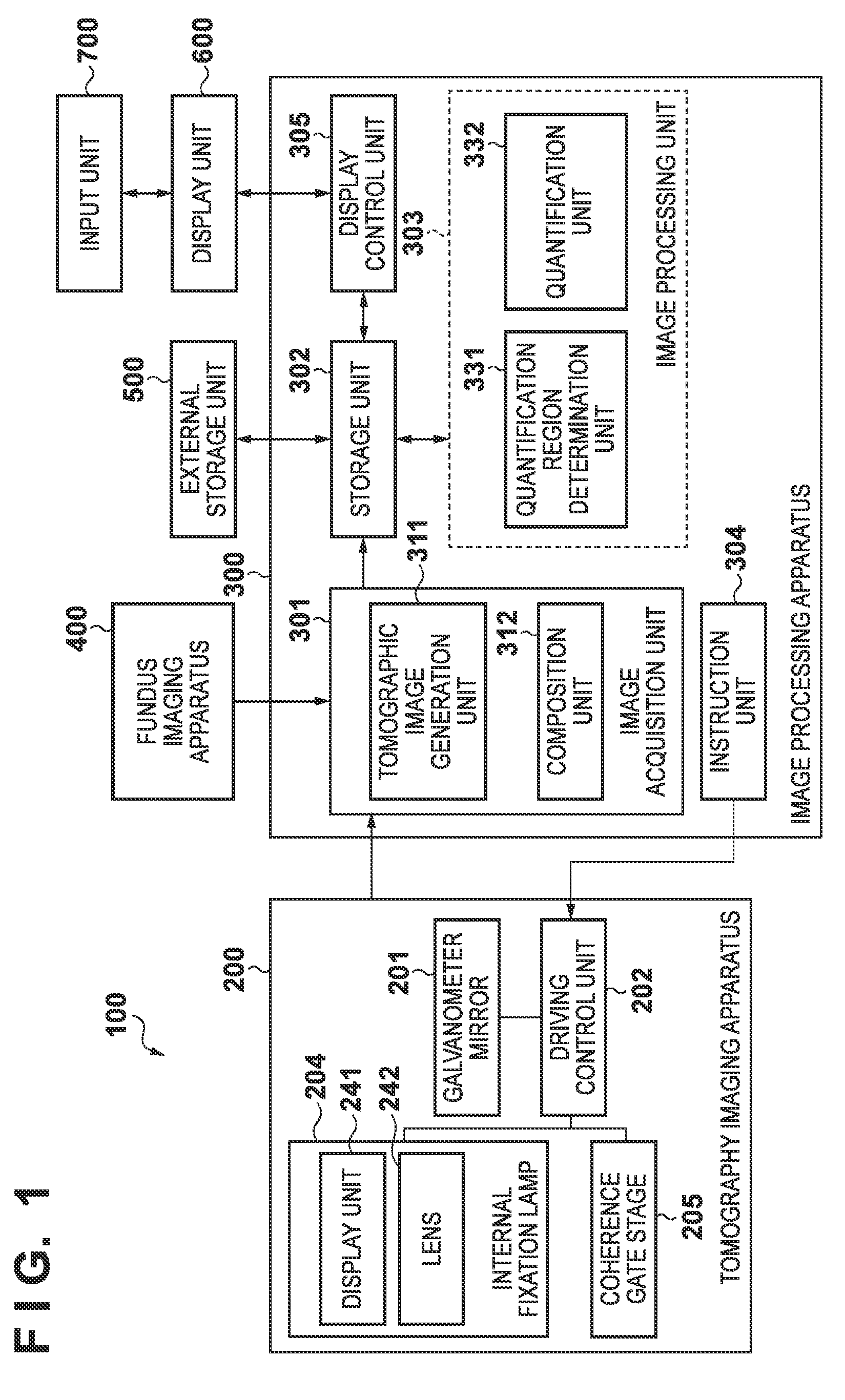
[0035]FIG. 1 is a block diagram showing the arrangement of an image processing system 100 including an image processing apparatus 300 according to this embodiment. As shown in FIG. 1, the image processing system 100 is constructed by connecting the image processing apparatus 300 to a tomography imaging apparatus (also referred to as an OCT) 200, a fundus imaging apparatus 400, an external storage unit 500, a display...
second embodiment
Fractal Analysis
[0073]In the first embodiment, an example has been described in which the quantification unit 332 thins the layer in the quantification region 32 and calculates the parallelness of the lines, thereby quantifying the degree of distortion in the layer. In the second embodiment, as an example in which the degree of distortion in a layer is quantified by another method, a method using fractal analysis will be explained. Note that in this embodiment, processing concerning quantification (step S205 of FIG. 2A) by a quantification unit 332 shown in FIG. 1 is different from the first embodiment. The remaining processes are the same as in the first embodiment, and a description thereof will be omitted.
[0074]To perform fractal analysis, the quantification unit 332 performs noise removal, line segment enhancement, and binarization as in steps S251 and S252. The quantification unit 332 then executes fractal analysis in a binarized quantification region 32. As the fractal analysi...
third embodiment
Analysis of Statistical Features of Texture
[0075]In the second embodiment, a method using fractal analysis as texture features has been described. In the third embodiment, a method using statistical features of texture will be explained. Note that in this embodiment, processing concerning quantification (step S205 of FIG. 2A) by a quantification unit 332 shown in FIG. 1 is different from the first embodiment. The remaining processes are the same as in the first embodiment, and a description thereof will be omitted.
[0076]The statistical features of texture characterize the texture by the statistical properties concerning the density distribution of a pixel set. In a healthy eye, the layers from the IS / OS to the RPE near the fovea of the macular portion are periodically arranged. On the other hand, if the eyesight is poor because of a diabetic macular edema, the layer structure from the IS / OS to the RPE is often lost or distorted. Hence, analyzing whether the layers in this region are...
PUM
 Abstract
Description
Claims
Application Information
 - R&D
- Intellectual Property
- Life Sciences
- Materials
- Tech Scout
- Unparalleled Data Quality
- Higher Quality Content
- 60% Fewer Hallucinations
Browse by: Latest US Patents, China's latest patents, Technical Efficacy Thesaurus, Application Domain, Technology Topic, Popular Technical Reports.
© 2025 PatSnap. All rights reserved.Legal|Privacy policy|Modern Slavery Act Transparency Statement|Sitemap|About US| Contact US: help@patsnap.com


