Eureka AIR delivers breakthrough ideas for toughest innovation challenges, trusted by R&D personnel around the world.

Renewable Energy Hot Water Heating Elements

a technology of renewable energy and hot water heating elements, applied in the direction of lighting and heating apparatus, heating types, immersion heating arrangements, etc., can solve the problems of increased operating costs and large water heaters for commercial applications, and achieve the effect of enhancing the efficiency of hot water generation, net metering, and/or the generation of renewable energy credits

Active Publication Date: 2013-10-10
KREUTZMAN DAVID
View PDF35 Cites 25 Cited by
  • Summary
  • Abstract
  • Description
  • Claims
  • Application Information

AI Technical Summary

Benefits of technology

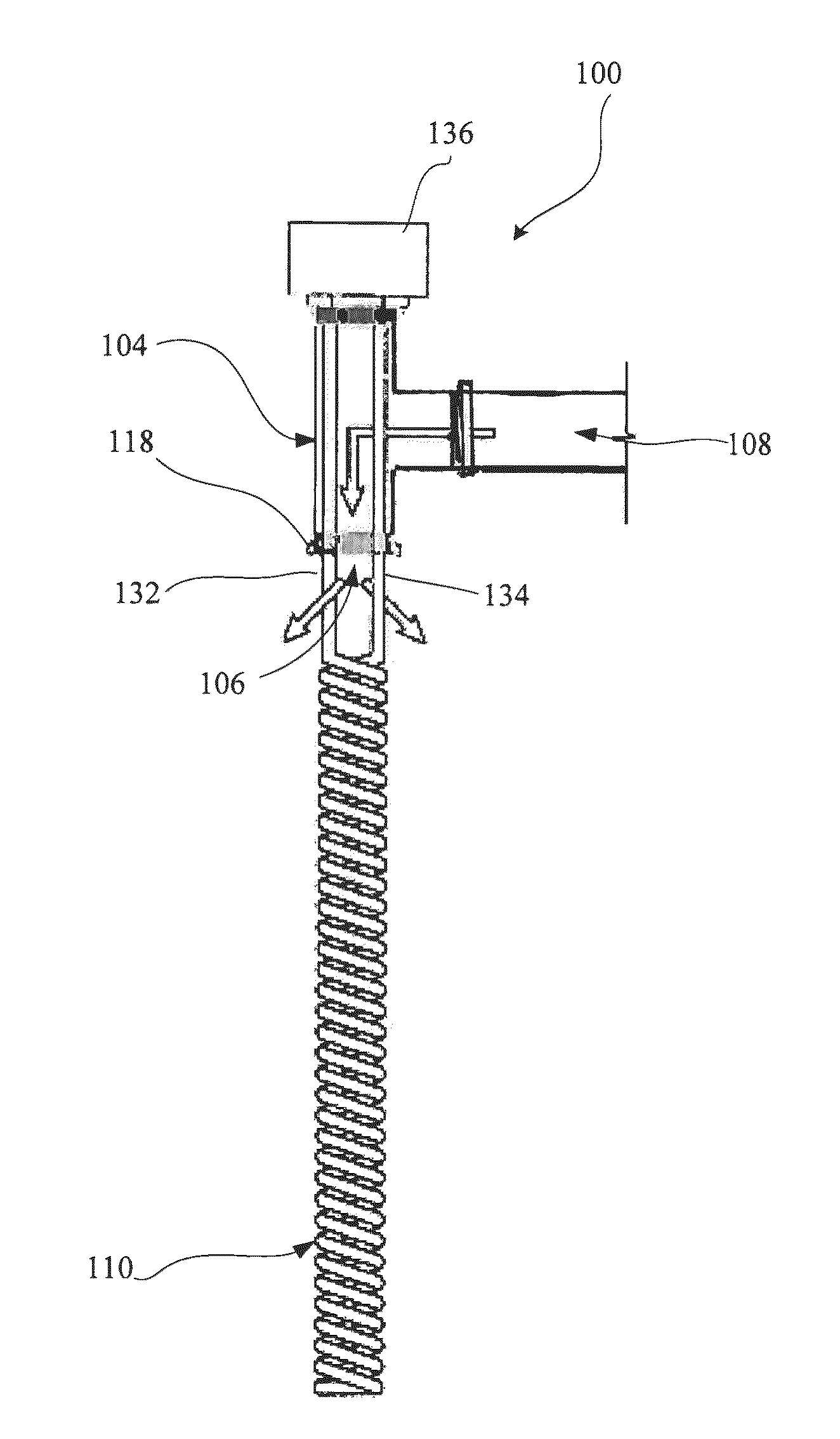
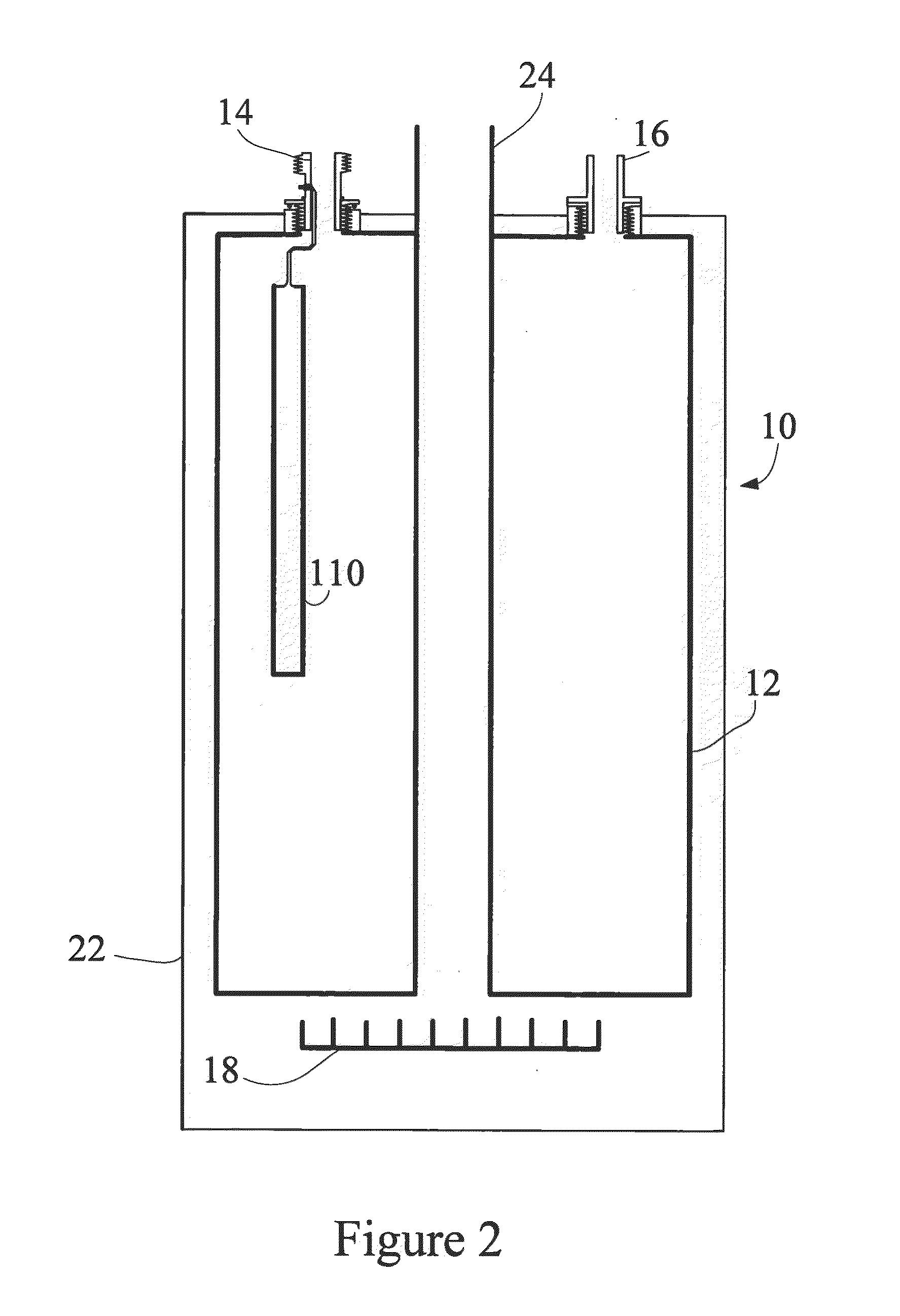
This patent discusses how to retrofit existing water heaters with electrical heating elements that can be powered by renewable energy sources. The system includes a threaded collar that is attached to the tank, allowing fluid to flow through it. The electrical connectors pass through a sidewall of the collar, which has a small cross-sectional area to reduce flow resistance. The system also includes control methods to improve efficiency and net metering. The technical effects of this patent are that it provides a way to generate hot water from renewable energy sources and improve the overall performance of the system.

Problems solved by technology

Water heaters for commercial applications are often much larger.
Electric water heaters have high efficiencies (e.g., above 95%) once the electricity enters the home but are more costly to operate due to electricity generation and transmission costs.

Method used


Image

  • Renewable Energy Hot Water Heating Elements
  • Renewable Energy Hot Water Heating Elements
  • Renewable Energy Hot Water Heating Elements

Examples


first embodiment

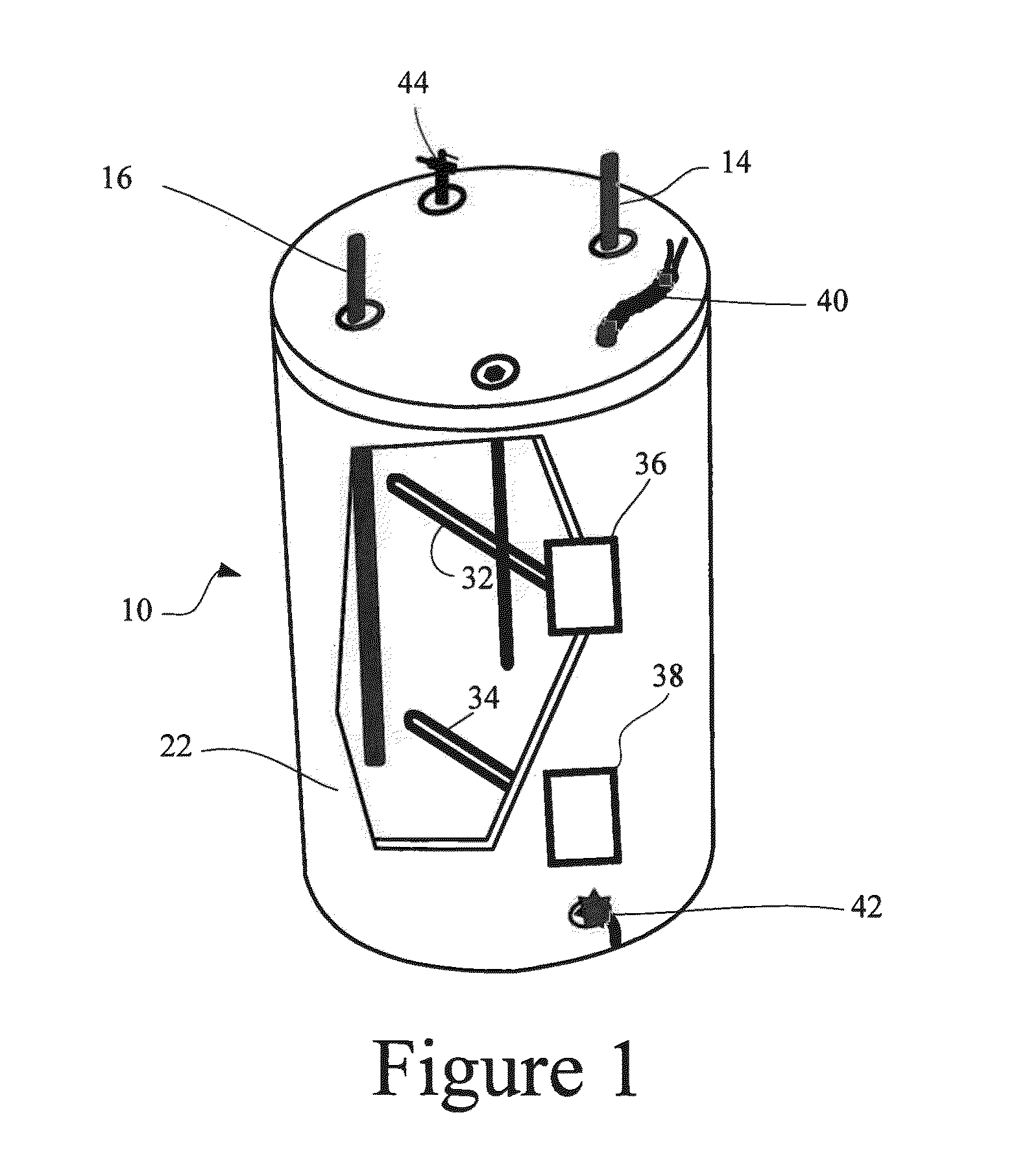
[0105]In a first embodiment, a controller 80, which in some arrangements may include an inverter, receives power from a renewable energy source 60 and is electrically interconnected to a junction box 312. The controller 80 provides electrical power from the renewable energy source to the junction box 312. In addition, the controller 80 controls a switch within the junction box 312 to selectively connect and disconnect the power sources. For instance, the switch may disconnect the AC source 310 when sufficient electrical power is received from the renewable energy source 60. In this regard, upon determining that the power from the renewable energy source is above a predetermined minimum, the AC power source 310 is disconnected and electrical energy from the renewable energy source 60 is provided directly to the heater element 32. The electrical energy provided from the renewable energy source 60 may be in the form of a DC current or, if inverter is utilized, in the form of an AC curr...

second embodiment

[0107]In a second embodiment, AC current may be provided from the renewable energy source to the heater element 32. In this embodiment, an inverter may be combined with the controller or otherwise disposed between the renewable energy source 60 and the junction box 312. In a further arrangement, micro-inverters may be mounted on each of the PV panels of the solar array. Micro-inverters produce utility matching power directly at the back of the panel. Such arrays of panels are connected in parallel to each other and fed to an application and / or to the grid. This has the major advantage that a single failing panel or inverter will not take the entire string of panels offline. In any arrangement utilizing an inverter, AC current may be fed to the heating element 32 to generate heat. Again, such a system may utilize a junction box 312 that disconnects the AC power source 310 prior to application of the AC current from the renewable energy source 60. Alternatively, a block-in diode 314 m...


PUM

PropertyMeasurementUnit
temperaturesaaaaaaaaaa
outlet temperatureaaaaaaaaaa
cross-sectional areaaaaaaaaaaa

Abstract

Provided herein are systems and methods directed to using renewable energy sources with hot water heating systems.

Description

FIELD[0001]Systems and methods (i.e., utilities) disclosed herein are directed to improvements to renewable energy hot water heating for residential and commercial applications.BACKGROUND[0002]In household and commercial usage, most hot water heaters in North America, as well as numerous other countries, are of a storage type. Such storage type water heaters typically include a cylindrical vessel / container (i.e., tank) in which water is kept continuously hot and ready for use. Typical sizes for household use range from about 20 to 120 U.S. gallons. Water heaters for commercial applications are often much larger. Heating the water in the tank may is typically affected by way of electrical heating elements or fossil fuel burners (e.g., natural gas, propane, fuel oil, bio mass, etc.) burners. Often, the source of the energy for heating is a local utility.[0003]In most hot water heaters, water is introduced into the storage tank via a water supply inlet pipe. Water typically enters resi...

Claims


Application Information

Patent Timeline
Patent Type & Authority Applications(United States)
IPC IPC(8): H05B3/82B23P6/00
CPCH05B3/82Y10T29/49352F24H1/205F24H9/0015F24H9/124F24H9/1818F24H9/2021F24H9/2035F24D2200/02F24D2200/043F24D2200/08F24D2200/32F24D2220/08F24D2220/10F24H1/202F24H9/133F24H15/414F24H15/281F24H15/219F24H15/292F24H15/315F24H15/223F24H15/174F24H15/36F24H15/457F24H15/395F24H15/164F24H15/172F24H15/37
Inventor KREUTZMAN, DAVID
Owner KREUTZMAN DAVID
Why Eureka
Eureka Blog
Learn More