Actuator support structure and pump device

Active Publication Date: 2013-10-10
MURATA MFG CO LTD
View PDF4 Cites 24 Cited by
  • Summary
  • Abstract
  • Description
  • Claims
  • Application Information

AI Technical Summary

Benefits of technology

The patent describes a configuration where the outer part of an actuator is connected and elastically supported on a side wall, allowing for displacement of the actuator. The elastic support portion is designed in a way that it can be configured in a straight or circular arc shape, ensuring a sufficient length without folding the beam portion. This allows for a wide range of beam portion lengths without reducing the size of the vibration plate. Additionally, the thin portion of the actuator vibrates with the vibrations of the actuator, increasing the vibration amplitude and fluid pressure and flow rate in the pump device.

Problems solved by technology

However, the pumping power of the pump device tends to decrease as the size is reduced or the drive voltage is decreased.
Thus, there are limits to the size reduction and the drive voltage decrease.

Method used


Image

  • Actuator support structure and pump device
  • Actuator support structure and pump device
  • Actuator support structure and pump device

Examples


first preferred embodiment

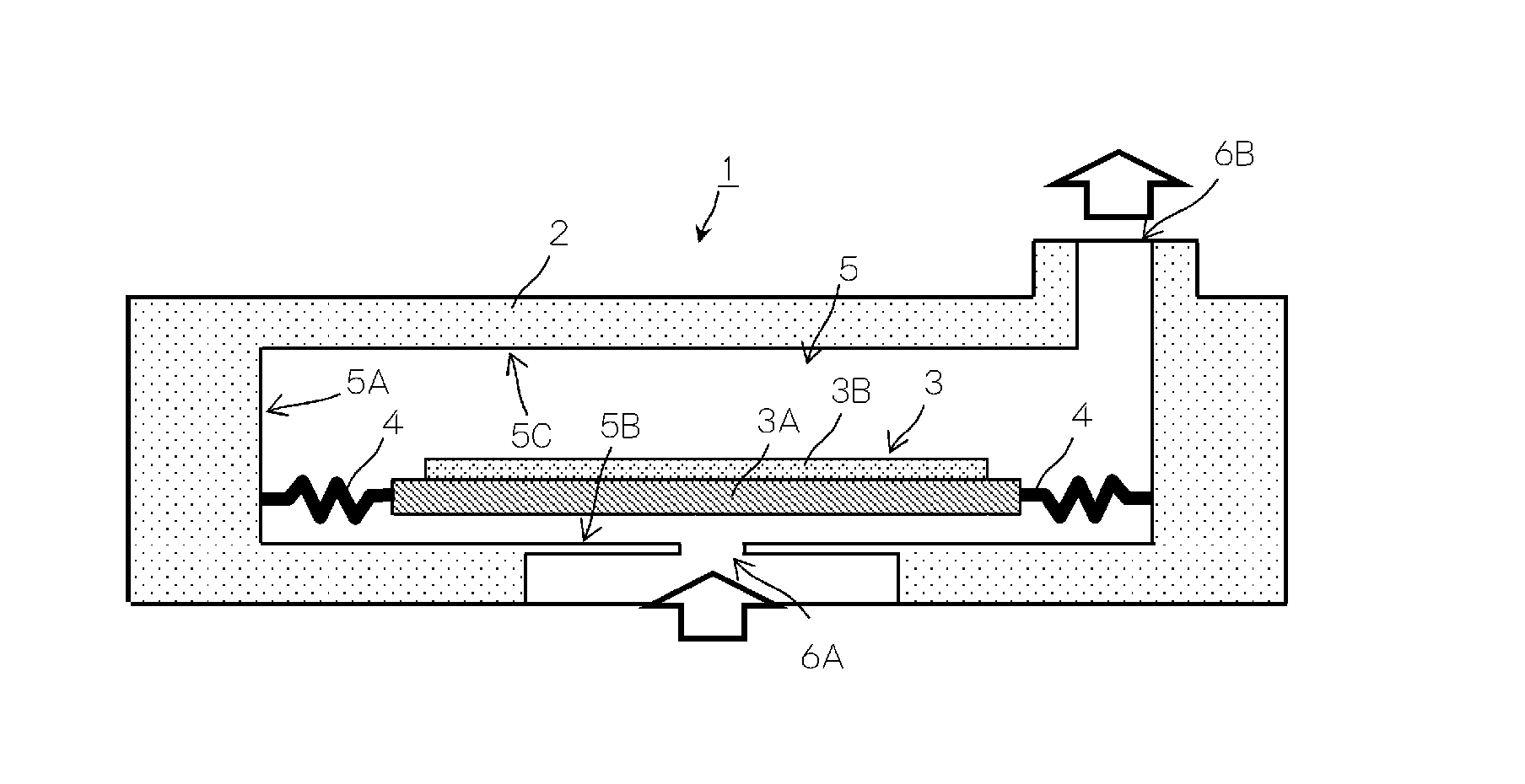
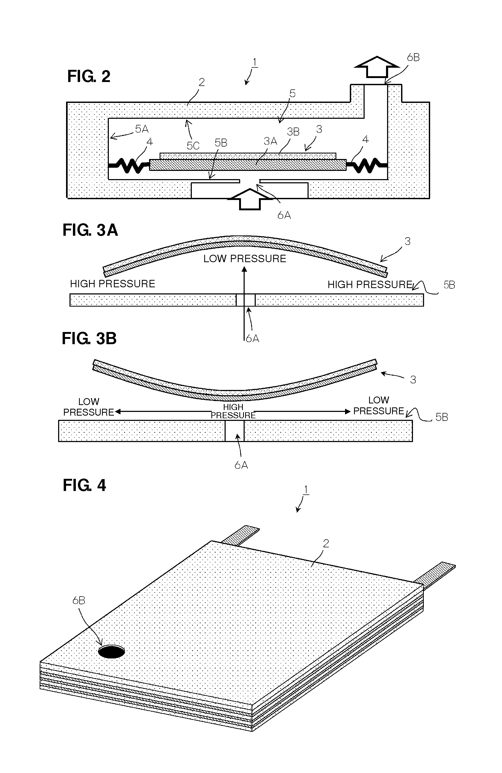
[0038]First, a schematic configuration of a piezoelectric pump 1 according to a first preferred embodiment of the present invention and its basic pumping action will be described.

[0039]FIG. 2 is a schematic cross-sectional view of the piezoelectric pump 1 according to the first preferred embodiment of the present invention during non-driving.

[0040]The piezoelectric pump 1 includes a housing 2, an actuator 3, and an elastic support portion 4.

[0041]The actuator 3 includes a piezoelectric element 3B attached to a vibration plate 3A. In the piezoelectric element 3B, electrode films which are not shown are preferably provided on substantially the entire upper and lower principal surfaces, respectively. The piezoelectric element 3B is configured to extensionally vibrate when, for example, a square-wave or sine-wave drive voltage of about 20 kHz is applied between these electrodes. Because of the configuration of the actuator 3 in which the piezoelectric element 3B is attached to the vibra...

second preferred embodiment

[0078]Next, a piezoelectric pump 51 according to a second preferred embodiment of the present invention will be described.

[0079]FIG. 10 is an exploded perspective view of the piezoelectric pump 51. The piezoelectric pump 51 includes an actuator 53 and a thin metal plate 58 each of which has a different configuration from that in the first preferred embodiment of the present invention described above.

[0080]The actuator 53 includes a piezoelectric element 3B, a reinforcing plate 55, a leaf spring 56, and a reinforcing plate 55 that are laminated in a middle portion thereof. In this case, it is necessary to appropriately reset the coefficient of linear expansion of each member, and it is preferable that a material having a sufficiently higher coefficient of linear expansion than those of the piezoelectric element 3B and the leaf spring 56 is used for the reinforcing plate 55. Preferably, for example, phosphor bronze, German silver, or other suitable material having a high coefficient o...


PUM


Abstract

A piezoelectric pump includes a leaf spring including a disc portion defining an actuator, an outer frame portion defining a housing, and an elastic support portion. The actuator flexurally vibrates from a center portion of a principal surface thereof to an outer periphery thereof. The elastic support portion includes a beam portion and connection portions and elastically supports the disc portion on the outer frame portion. The beam portion extends in a gap between the disc portion and the outer frame portion in a direction along an outer periphery of the disc portion. A first of the connection portions connects the beam portion to the disc portion. Second and third connection portions are offset from the first connection portion and connect the beam portion to the outer frame portion.

Description

BACKGROUND OF THE INVENTION[0001]1. Field of the Invention[0002]The present invention relates to an actuator support structure that supports an actuator which flexurally vibrates and a pump device that includes the actuator support structure and conveys fluid.[0003]2. Description of the Related Art[0004]A thin pump device has been developed which is used for conveying air for a fuel cell system and other devices, and controls the flow of fluid by using an actuator that flexurally vibrates (e.g., see International Publication No. 2008 / 069264).[0005]FIG. 1 is a diagram illustrating an example of an existing pump device and its action.[0006]The pump device 100 includes an actuator 110 including a vibration plate 111 and a piezoelectric element 112 and an opposed plate 101 disposed so as to be adjacent to and opposed to the vibration plate 111. The vibration plate 111 is made of metal and fixed at the entire outer peripheral portion thereof to the opposed plate 101. The piezoelectric el...

Claims


Application Information

Patent Timeline
IPC IPC(8): F04B45/047
CPCF04B17/003F04B45/047H01L41/0973F04B43/046H10N30/2047F04B43/0054F04B2203/0406
Inventor HIRATA, ATSUHIKOKODAMA, YUKIHARUOMORI, KENTA
Owner MURATA MFG CO LTD
Why Eureka
Try Eureka