Glow plug with combustion pressure sensor

a technology of combustion pressure sensor and glow plug, which is applied in the field of glow plug, can solve the problems of low accuracy in detecting combustion pressure and limit the area of the connecting member

Inactive Publication Date: 2013-10-17
NGK SPARK PLUG CO LTD
View PDF16 Cites 10 Cited by
  • Summary
  • Abstract
  • Description
  • Claims
  • Application Information

AI Technical Summary

Problems solved by technology

However, in the glow plug described in Patent Document 1, since the connecting member is connected to the large-diameter section of the heater unit, a limitation is imposed on the area of the connecting member.
Therefore, the amount of axial displacement permitted for the heater unit is not sufficient, so that the accuracy in detecting combustion pressure may be low.

Method used


Image

  • Glow plug with combustion pressure sensor
  • Glow plug with combustion pressure sensor
  • Glow plug with combustion pressure sensor

Examples


Embodiment Construction

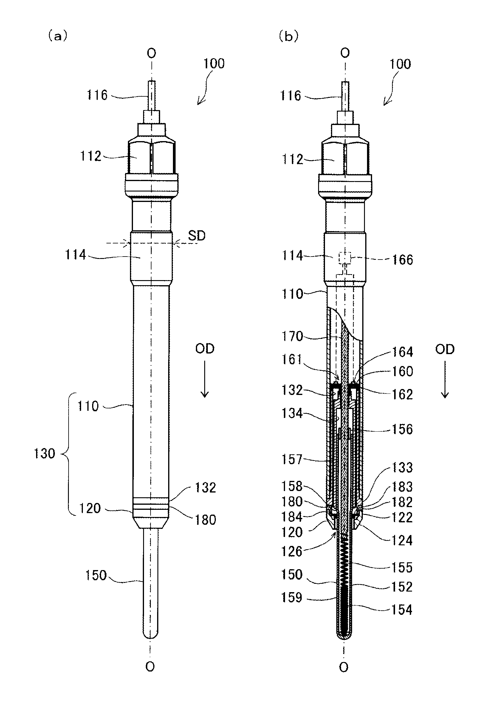
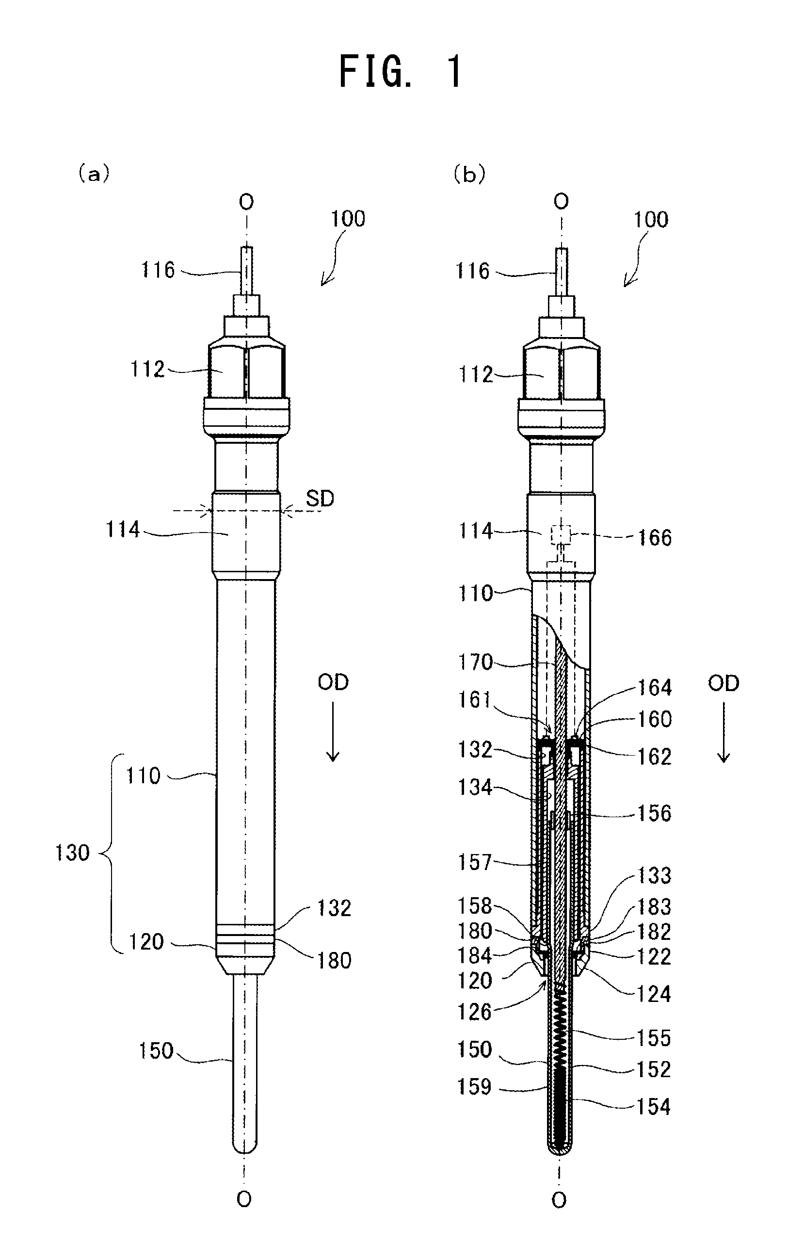
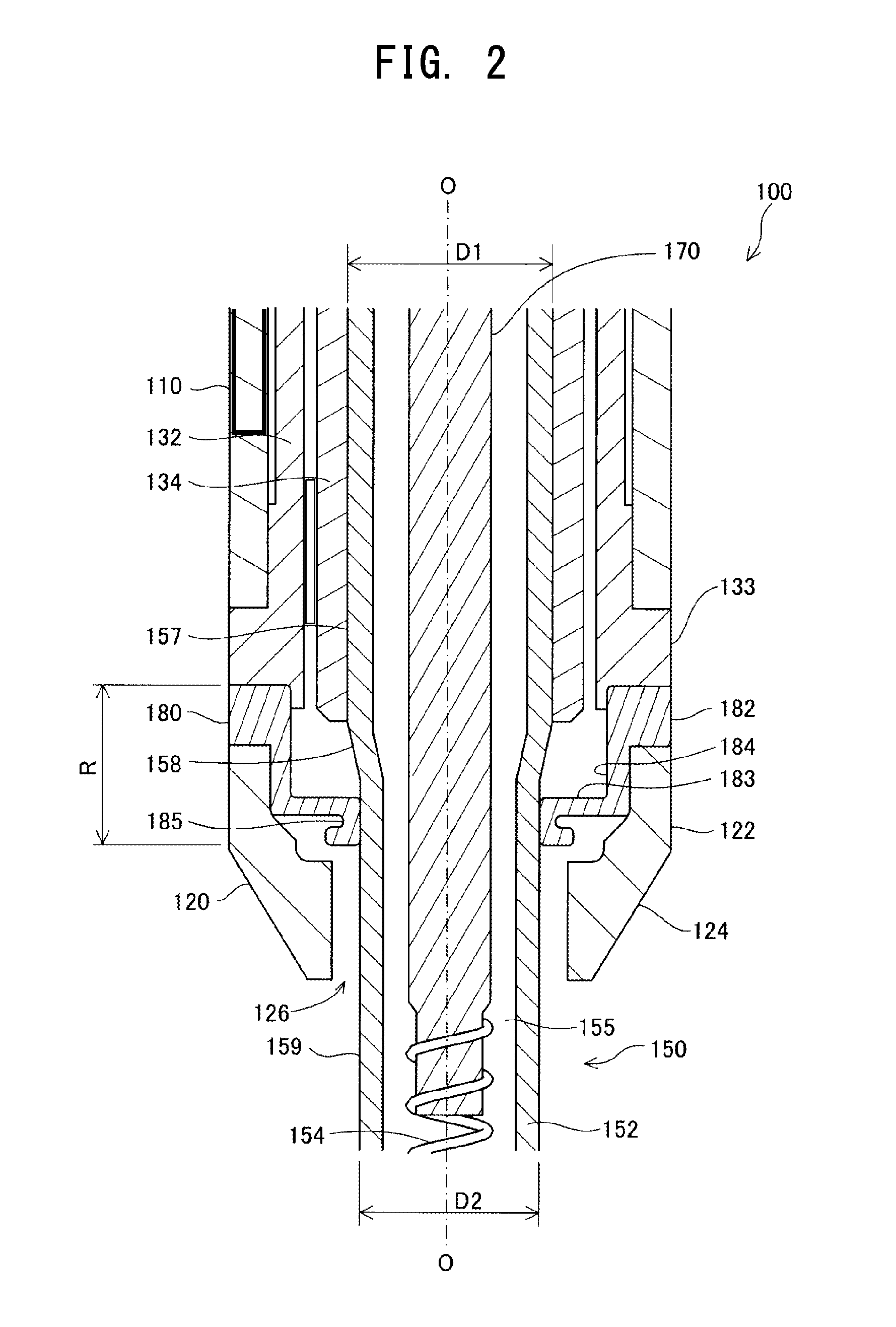
[0025]FIG. 1 is a set of diagrams illustrating the structure of a glow plug 100 according to one embodiment of the present invention. FIG. 1(a) shows the overall structure of the glow plug 100, and FIG. 1(b) is a partially sectioned view showing the structure. FIG. 2 is an enlarged cross-sectional view of the vicinity of a connecting member 180 to be described later. In the following description, the lower side of the glow plug 100 along an axis O in FIGS. 1 and 2 is referred to as the front side of the glow plug 100, and the upper side is referred to as the rear side. In addition, a downward direction along the axis O of the glow plug 100 is referred to as an axial direction OD. As shown in FIGS. 1(a) and 1(b), the glow plug 100 comprises a housing 130 including a metallic shell 110 and a cap member 120, and a heater unit 150.

[0026]The metallic shell 110 is a substantially cylindrical metal member formed of carbon steel or stainless steel. A tool engagement portion 112 for engageme...


PUM


Abstract

A glow plug including a substantially cylindrical housing extending in an axial direction; a rod-shaped heater unit having a front end protruding from the front end of the housing and movable in the axial direction; a connecting member connecting the heater unit to the housing within the housing and allowing the heater unit to move in the axial direction; and a pressure sensor that detects pressure received by the heater unit. The heater unit has a large-diameter portion at the rear end thereof and a small-diameter portion frontward of the large-diameter portion and having a diameter smaller than the diameter of the large-diameter portion. The connecting member connects the small-diameter portion of the heater unit to the housing within the housing.

Description

TECHNICAL FIELD[0001]The present invention relates to a glow plug and particularly to a glow plug with a combustion pressure sensor.BACKGROUND ART[0002]One of widely known conventional glow plugs used in internal combustion engines such as diesel engines is a glow plug equipped with a pressure sensor for detecting combustion pressure in an internal combustion engine. Such a glow plug typically includes a housing, and a heater unit protruding from the housing. For example, Patent Document 1 discloses a glow plug including a heater unit (finger) which is reduced in diameter stepwise such that the heater unit has a small-diameter front portion and a large-diameter rear portion. The heater unit of the glow plug described in Patent Document 1 is connected to a housing (body) through a membrane-like connecting member that allows the heater unit to move in an axial direction. A sensor disposed in the glow plug detects the axial displacement of the heater unit to thereby detect combustion p...

Claims


Application Information

Patent Timeline
Patent Type & Authority Applications(United States)
IPC IPC(8): F23Q7/00
CPCF23Q7/001F02D35/023F02P19/028F23Q2007/002F02P19/00F23Q7/00G01L23/22F23Q2007/005
Inventor NAKAMURA, YOSHIHIROMAEDA, SHUNSUKEWATANABE, TADASHIMATSUI, MASAYOSHI
Owner NGK SPARK PLUG CO LTD
Why Eureka
Try Eureka