Heat exchanger

a technology of heat exchanger and heat exchanger body, which is applied in the direction of indirect heat exchangers, lighting and heating apparatus, and separation processes, etc., can solve the problems of many known heat exchangers, affecting the efficiency affecting the operation of the heat exchanger itself, so as to reduce the weight, bulk and load loss, and reduce the effect of air path deflection

Inactive Publication Date: 2013-10-17
OFF MEC INDALI CON UNICO SOCIO
View PDF2 Cites 8 Cited by
  • Summary
  • Abstract
  • Description
  • Claims
  • Application Information

AI Technical Summary

Benefits of technology

[0019]In this way it is possible to obtain a configuration of the exchanger that is more compact at least along the same longitudinal direction. Indeed, the fact that the two axes of longitudinal development are disposed angled and incident with respect to each other allows to reduce the longitudinal bulk compared with known heat exchangers.
[0037]In this way, the maintenance of the heat exchanger is easy, because it may only involve one of its components, without needing to remove or replace the whole heat exchanger in the event of breakdowns, malfunctions or simple controls.

Problems solved by technology

On the other hand however, it has the disadvantage that, if high cooling powers are required, the components have to be very long, and this is harmful for the efficiency of the exchanger itself, and often excessive for the requirements of the plant where they have to be installed.
In the light of this, many known heat exchangers therefore have the disadvantage that they can be applied only in plants that do not have particularly restrictive geometrical limitations.
Known heat exchangers, of the horizontal or vertical type and with aligned components, also have the disadvantage that they cannot exploit the natural circulation of fluids due to the force of gravity, requiring apparatuses to move the fluids.
This arrangement involves complexity of work, less thermal efficiency and a bulky overall structure.
EP-A2-149.466 and DE 10 2010 008383 A1 disclose other configurations of heat exchangers with elements angled each other, but also these arrangements have complex and bulky configurations of the connections between the channels of one and the other exchangers.

Method used


Image

  • Heat exchanger
  • Heat exchanger
  • Heat exchanger

Examples


Embodiment Construction

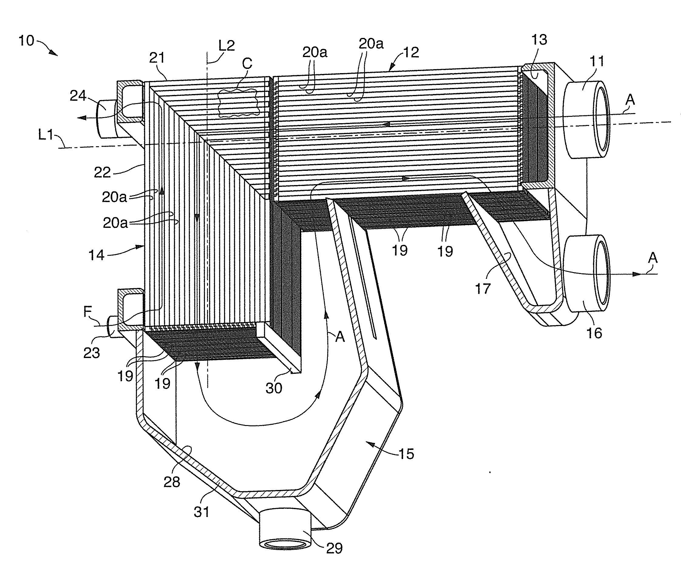
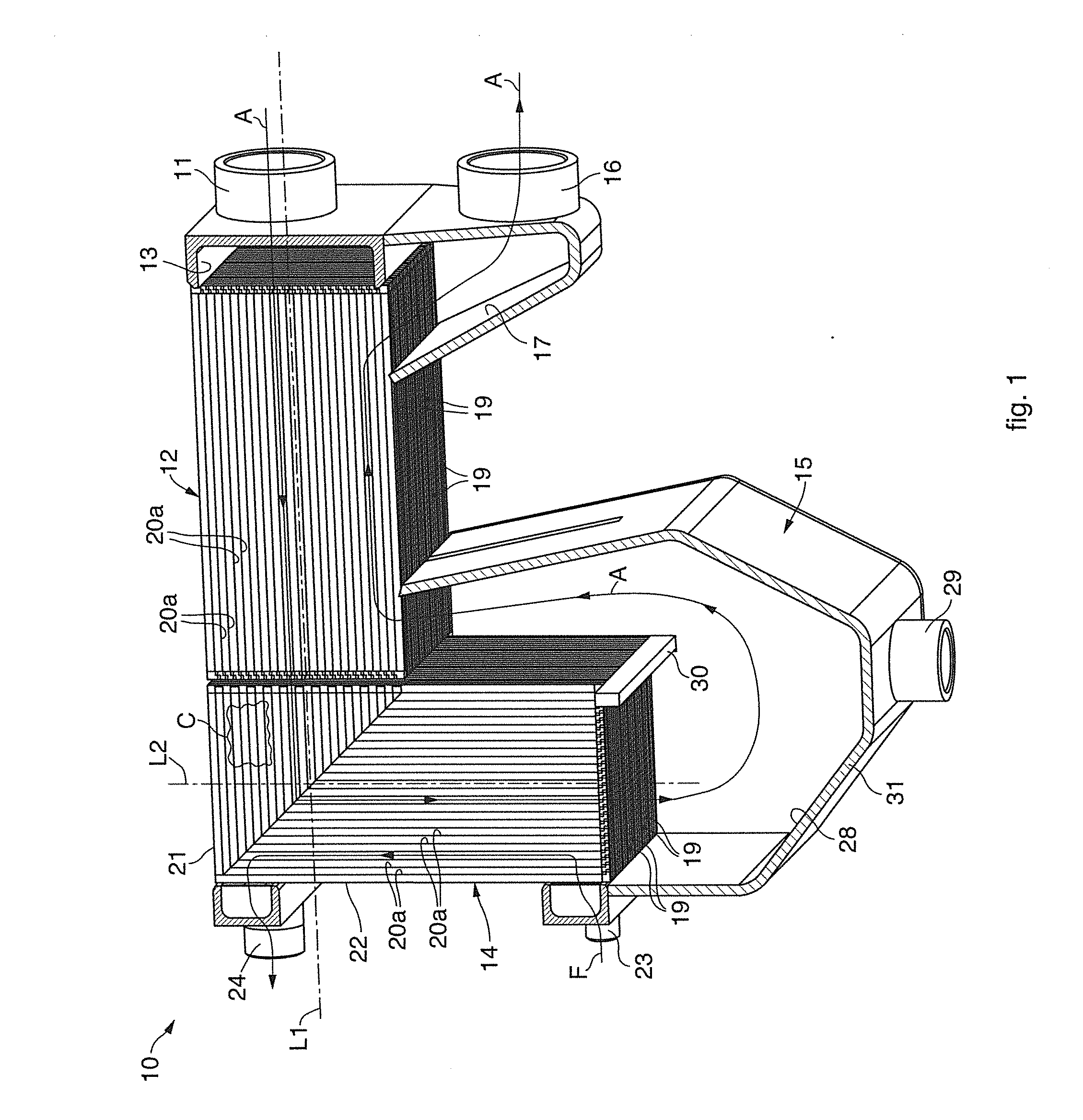
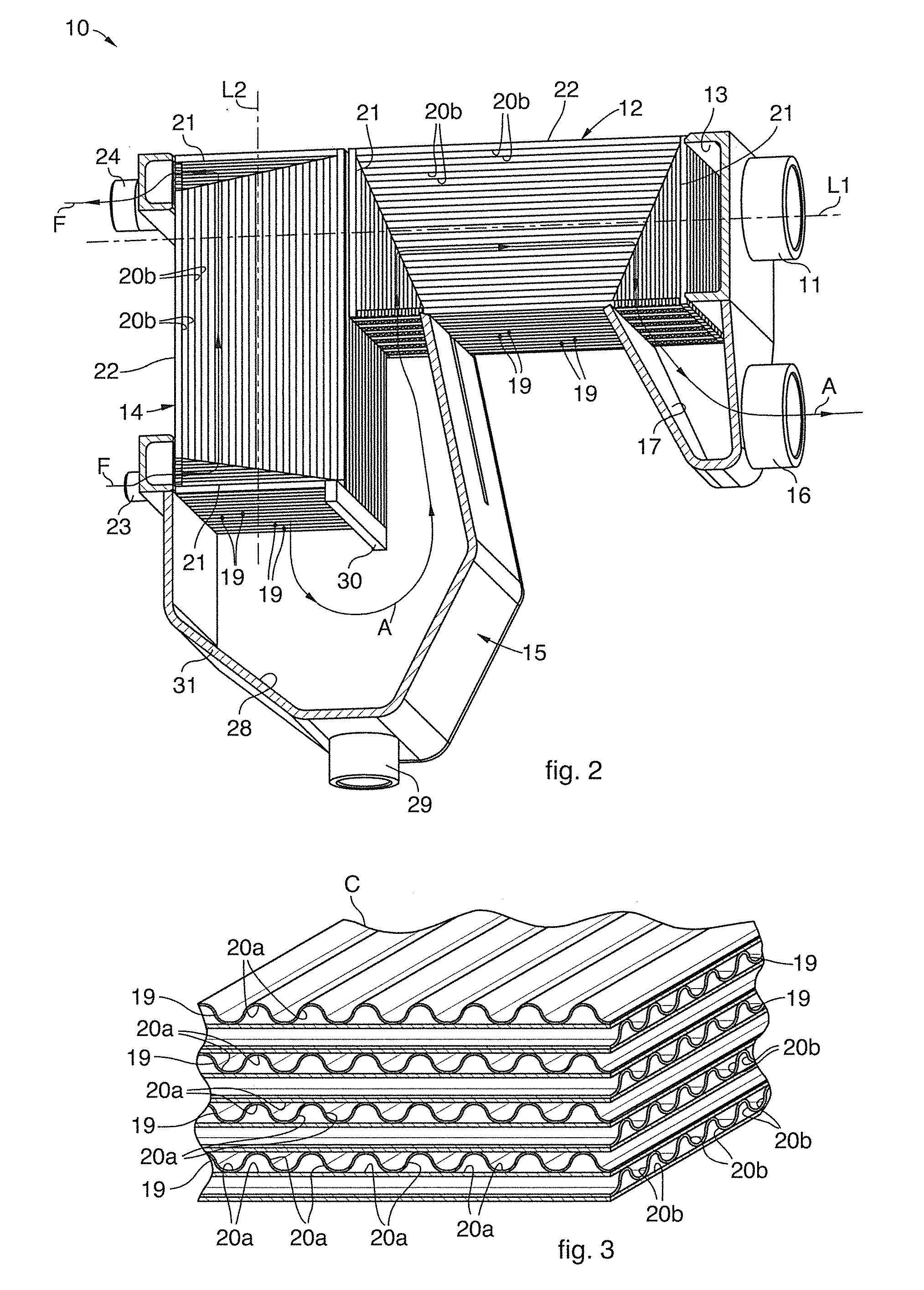
[0051]With reference to FIGS. 1 and 2, a heat exchanger 10 according to the present invention is suitable to allow the exchange of heat between a stream of hot fluid, in this case air A, to be cooled, and a stream of cooling fluid, in this case freon F.

[0052]The heat exchanger 10 comprises a pre-cooling unit, or pre-exchanger 12, a cooling unit or evaporator 14, and a unit to separate the condensation, or separator 15.

[0053]In use, the heat exchanger 10 is positioned so that the pre-exchanger 12 and the evaporator 14 are disposed above the separator 15 and that the air A and the freon F enter and exit laterally from the heat exchanger 10.

[0054]The path of air A inside the heat exchanger 10 is shown in FIGS. 1 and 2, and is articulated as described hereafter.

[0055]Hot air A enters the exchanger 10 from an entrance pipe 11 positioned at one end of the pre-exchanger 12, and is distributed uniformly over the whole height of the latter by an entrance collector 13, so that the largest hea...


PUM


Abstract

A heat exchanger comprises at least a pre-cooling unit, or pre-exchanger, having a longitudinal development along at least a first longitudinal axis, and at least a cooling unit, or evaporator, having a longitudinal development along at least a second longitudinal axis and connected to the pre-exchanger in order to define a fluid-dynamic circuit for the circulation of a fluid, such as air, in said pre-exchanger and said evaporator. The first longitudinal axis and said second longitudinal axis are angled with respect to each other by an angle comprised between 45° and 135°.

Description

FIELD OF THE INVENTION[0001]The present invention concerns a heat exchanger used in cooling or drying machines and / or plants, such as for example drying plants for compressed air, or in general for applications where de-humidified and almost totally dry compressed air is required.[0002]Apart from in driers for compressed air, the invention is also advantageously applicable in industrial, commercial and residential cooling plants, or any other similar or comparable application.BACKGROUND OF THE INVENTION[0003]It is known to produce heat exchangers consisting of a pre-cooling unit, or so-called air-air pre-exchanger, a cooling unit, or so-called cooling air exchanger or evaporator, and a separation unit, to separate from the cooled fluid the condensation that has accumulated due to the cooling. At top and tail of such circuits there are collectors, in turn connected to the entrance and exit of the respective fluids.[0004]The pre-cooling unit and the cooling unit consist of a plurality...

Claims


Application Information

Patent Timeline
Patent Type & Authority Applications(United States)
IPC IPC(8): F28D15/00
CPCF28D15/00B01D53/265F28F9/26F28D9/0037F28D9/0093F28D2021/0038
Inventor DE PIERO, PAOLOVEZIL, STEFANODODDI, LUCA VITOCAPELLARI, GIOVANNI BATTISTA
Owner OFF MEC INDALI CON UNICO SOCIO
Why Eureka
Try Eureka