Power module
a power module and power technology, applied in the field of power modules, can solve the problems of reducing the design freedom of the terminal shape and the size of the external electrode, affecting the fatigue life direct, and increasing the size and cost of the power module, so as to achieve the effect of high degree of freedom in design, increased life span and low cos
- Summary
- Abstract
- Description
- Claims
- Application Information
AI Technical Summary
Benefits of technology
Problems solved by technology
Method used
Image

Examples
embodiment 1
Preferred Embodiment 1
Configuration
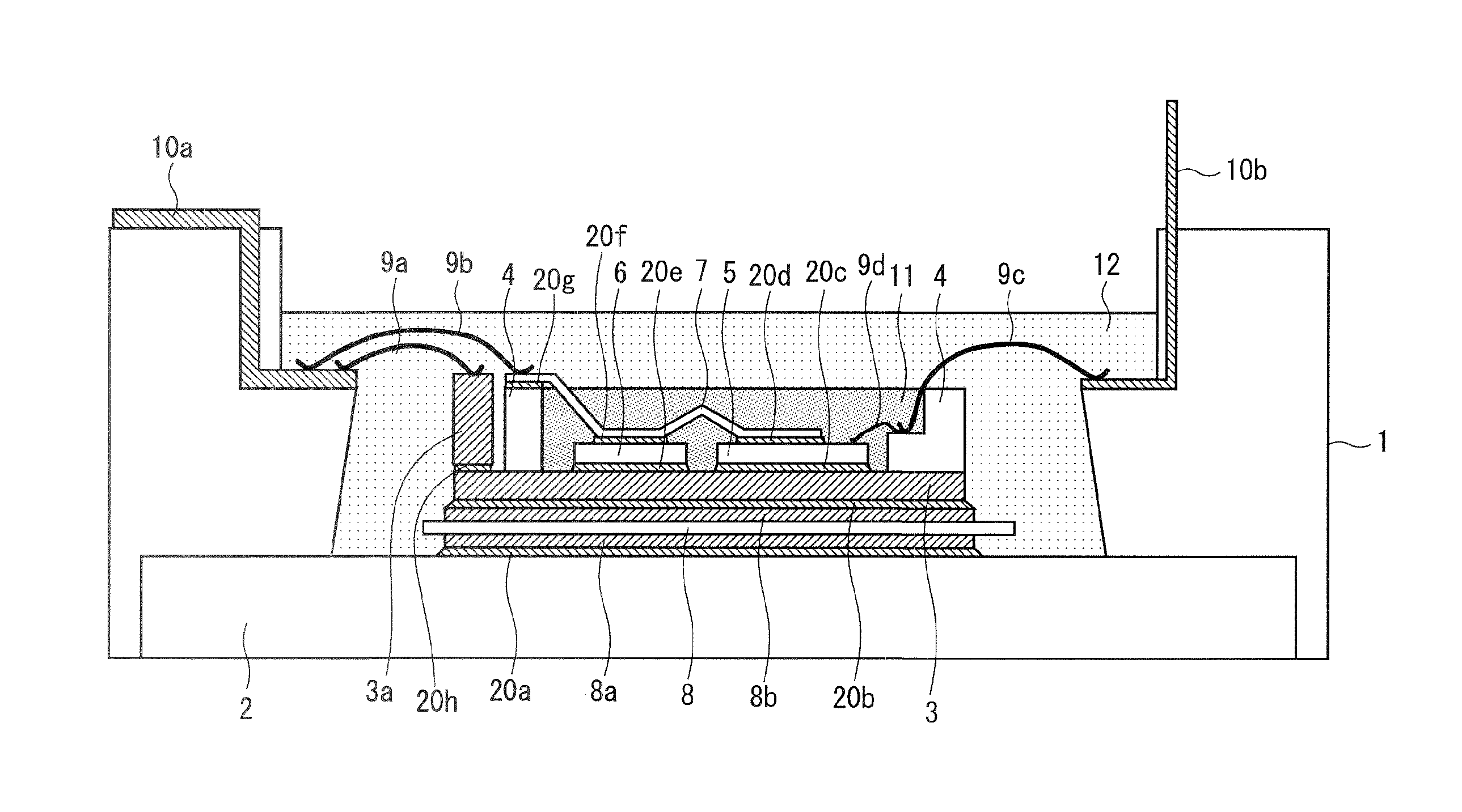
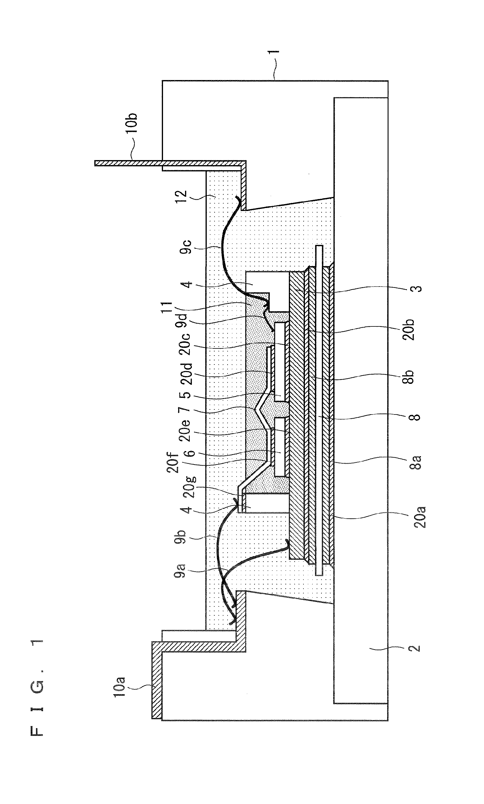
[0020]FIG. 1 shows a cross section of a power module according to this preferred embodiment. The power module of this preferred embodiment is configured such that each electrode of a power device chip 5, which is provided on and electrically bonded to a heat spreader 3 arranged within an outer casing 1, is connected to an external electrode 10a, an external electrode (not shown) located behind the external electrode 10a, and an external signal electrode 10b. The external electrode 10a, the external electrode (not shown) located behind the external electrode 10a, and the external signal electrode 10b are integrated with the power module.
[0021]A current applied to the external signal electrode 10b is adjusted, and thereby the power device chip 5 is turned on and off, and a main current flowing between the external electrode 10a and the external electrode located behind the external electrode 10a is controlled.
[0022]For the power device chip 5, for ex...
embodiment 2
Preferred Embodiment 2
[0058]FIG. 4 shows a cross section of a power module according to this preferred embodiment. In this preferred embodiment, instead of bonding the thick aluminum wire 9a directly on the heat spreader 3 as in the preferred embodiment 1 (FIG. 1), the thick aluminum wire 9a is bonded to an upper surface of a conductive electrode block 3a that is solder-bonded to the heat spreader 3. The other parts of the structure are the same as those of the preferred embodiment 1, and therefore descriptions thereof are omitted.
[0059]The electrode block 3a is bonded on a part of the heat spreader 3 located outside the dam 4, with interposition of the solder bonding portion 20f therebetween. The height of the electrode block 3a is the same as the height of the other end of the internal main electrode 7. From the viewpoint of the wire bonding, it is preferable that an error in the height is about ±0.3 mm. It is preferable that the material of the electrode block 3a is copper, which...
embodiment 3
Preferred Embodiment 3
[0063]This preferred embodiment is different from the preferred embodiment 1 in that, in a bonding surface between the insulating substrate and the heat spreader 3 shown in FIG. 1, that is, in a bonding surface between the metal pattern 8b and the heat spreader 3, a solder resist 21 is applied in advance to an outer circumferential portion of the metal pattern 8b and then the solder-bonding is performed. The other parts are the same as those of the preferred embodiment 1, and therefore descriptions thereof are omitted.
[0064]FIG. 5 shows the bonding surface between the insulating substrate and the heat spreader 3. The metal pattern 8b is formed on the ceramic insulating plate 8. As shown in FIG. 1, the metal pattern 8b and the heat spreader 3 are bonded to each other with interposition of the solder bonding portion 20b therebetween.
[0065]Before the metal pattern 8b and the heat spreader 3 are solder-bonded, the solder resist 21 is applied in advance to the outer...
PUM
 Abstract
Description
Claims
Application Information
 - R&D
- Intellectual Property
- Life Sciences
- Materials
- Tech Scout
- Unparalleled Data Quality
- Higher Quality Content
- 60% Fewer Hallucinations
Browse by: Latest US Patents, China's latest patents, Technical Efficacy Thesaurus, Application Domain, Technology Topic, Popular Technical Reports.
© 2025 PatSnap. All rights reserved.Legal|Privacy policy|Modern Slavery Act Transparency Statement|Sitemap|About US| Contact US: help@patsnap.com