Determination of a control sequence for a magnetic resonance imaging system

a magnetic resonance imaging and control sequence technology, applied in the direction of magnetic measurement, geological measurement, reradiation, etc., can solve the problem of severe generation of perceptible nois

Active Publication Date: 2013-10-17
SIEMENS HEALTHCARE GMBH
View PDF6 Cites 21 Cited by
  • Summary
  • Abstract
  • Description
  • Claims
  • Application Information

AI Technical Summary

Benefits of technology

[0016]An object of the present invention is to alleviate the problems associated with known methods that are described above.

Problems solved by technology

Due to interaction forces (Lorentz forces) of these currents with the basic magnetic field of the tomography system and the interaction of magnetic scatter fields of the gradient coil system (eddy current forces) with conductive regions of the tomography system, strong mechanical oscillations of the gradient coil system occur that—in addition to a high stress to the tomography system in mechanical terms—lead to severe generation of perceptible noise.

Method used


Image

  • Determination of a control sequence for a magnetic resonance imaging system
  • Determination of a control sequence for a magnetic resonance imaging system
  • Determination of a control sequence for a magnetic resonance imaging system

Examples


Embodiment Construction

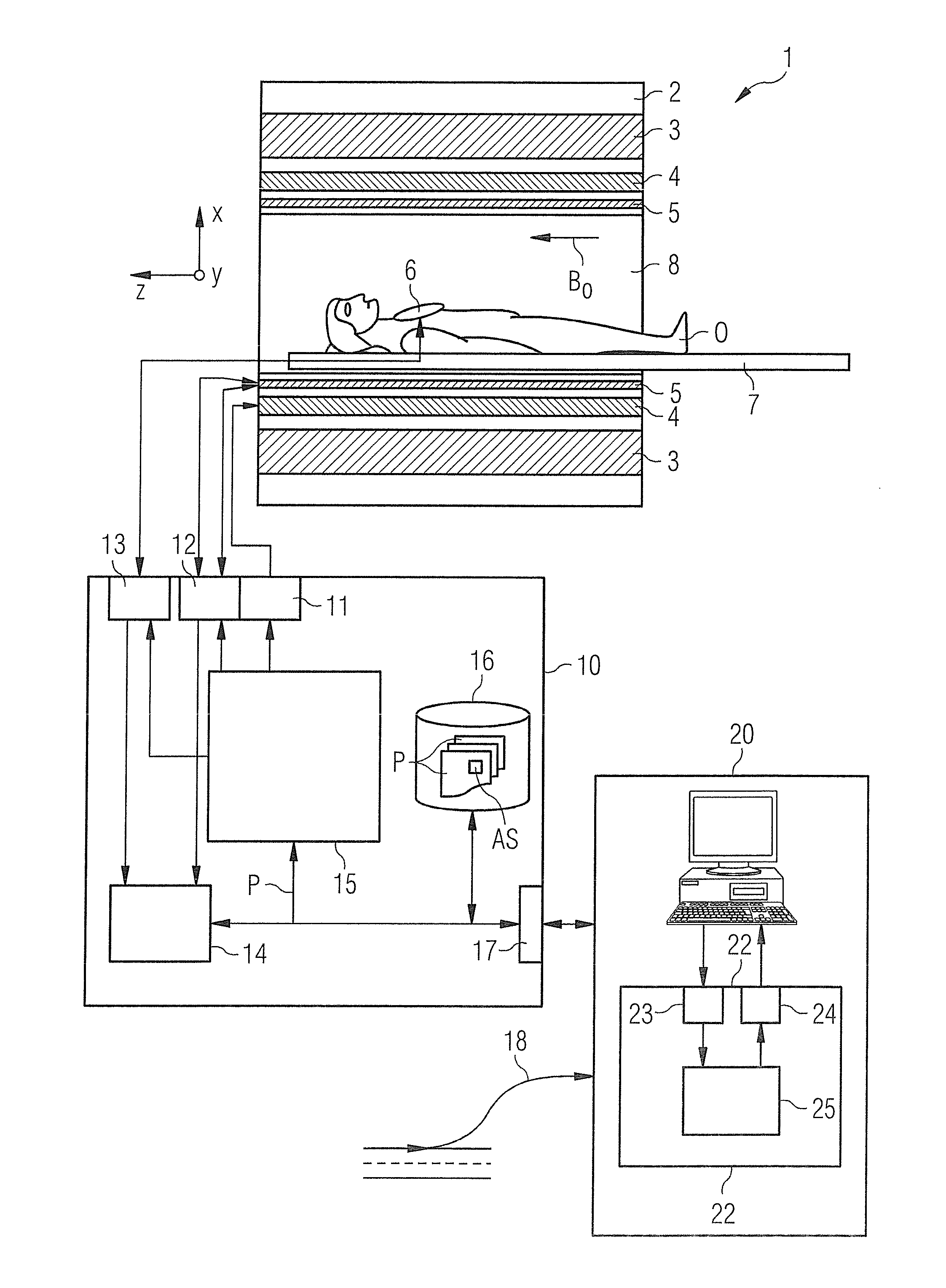
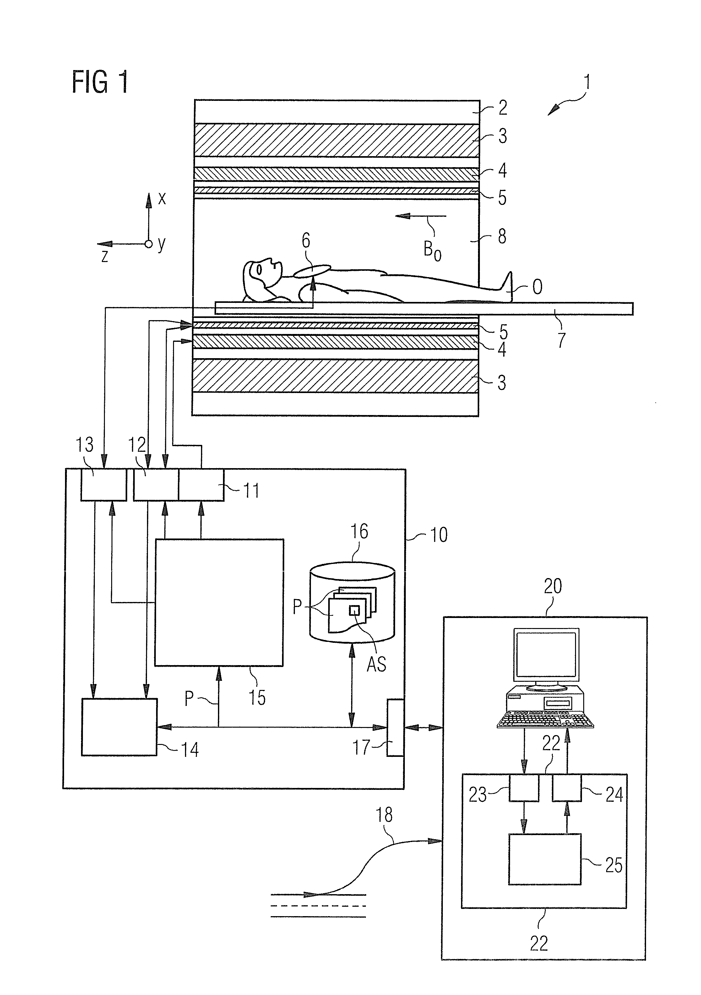
[0088]A magnetic resonance imaging system 1 according to the invention is shown in schematic form in FIG. 1. The imaging system 1 includes the actual magnetic resonance scanner (data acquisition unit) 2 with a measurement space or patient tunnel 8 located therein. A bed 7 can be driven into this patient tunnel 8 so that a patient O or test subject thereupon can be supported at a specific position within the magnetic resonance scanner 2 relative to the gradient coil system 4 arranged therein during an examination or can be driven between different positions during a measurement (data acquisition).

[0089]Basic components of the magnetic resonance scanner 2 include a basic field magnet 3 to generate a basic magnetic field B0, the gradient coil system 4 with gradient coils in order to apply nearly any gradient magnetic fields in the x-, y- and z-directions, and a whole-body radio-frequency coil 5. The reception of magnetic resonance signals produced in the test subject or examination sub...


PUM


Abstract

In a method to determine a control sequence for a magnetic resonance imaging system in order to acquire echo signal-based raw magnetic resonance data in k-space along one or more trajectories on the basis of the control sequence, the control sequence is optimized so that, to control a gradient magnetic field for at least a predetermined portion of the control sequence, a change of an attribute of the gradient magnetic field is limited. The limitation takes place so that a momentary amplitude change rate of the gradient magnetic field falls below a predetermined amplitude change rate limit value, and/or so that a momentary direction change rate of the gradient magnetic field falls below a predetermined direction change rate limit value, and/or so that a momentary gradient change rate of the gradient magnetic field that is based on a combination of the momentary amplitude change rate and the momentary direction change rate falls below a predetermined gradient change rate limit value.

Description

BACKGROUND OF THE INVENTION[0001]1. Field of the Invention[0002]The invention concerns a method to determine a control sequence for a magnetic resonance imaging system, and a method to operate a magnetic resonance imaging system, a control sequence determination device to determine a control sequence for a magnetic resonance imaging system; and a magnetic resonance imaging system with such a control sequence determination device.[0003]2. Description of the Prior Art[0004]Magnetic resonance imaging procedures have found numerous usage, for example for medical applications as well as for non-destructive material and structural analysis of components and other examination subjects. In a magnetic resonance imaging system, for data acquisition a static basic magnetic field is typically overlaid with a targeted, spatially differing magnetic field (known as the gradient magnetic field). The basic magnetic field serves for the initial alignment and homogenization of magnetic dipoles (i.e. o...

Claims


Application Information

Patent Timeline
Patent Type & Authority Applications(United States)
IPC IPC(8): G01R33/54
CPCG01R33/543G01R33/3854G01R33/482G01R33/4824
Inventor GRODZKI, DAVIDHEISMANN, BJOERN
Owner SIEMENS HEALTHCARE GMBH
Why Eureka
Try Eureka