
Apparatus and method for finding the direction of signal source

Inactive Publication Date: 2013-10-17
ELECTRONICS & TELECOMM RES INST
View PDF5 Cites 29 Cited by
  • Summary
  • Abstract
  • Description
  • Claims
  • Application Information

AI Technical Summary

Benefits of technology

The present invention provides an apparatus for finding the direction of a signal source that has a simple configuration and can be used over a wide range of frequencies. It uses a single phase detector and a single AOA calculator, reducing manufacturing costs. Additionally, it allows for easy adjustment of the distance between two antennas to calculate AOA, resulting in improved accuracy and reduced errors in regions close to 90 degrees.

Problems solved by technology

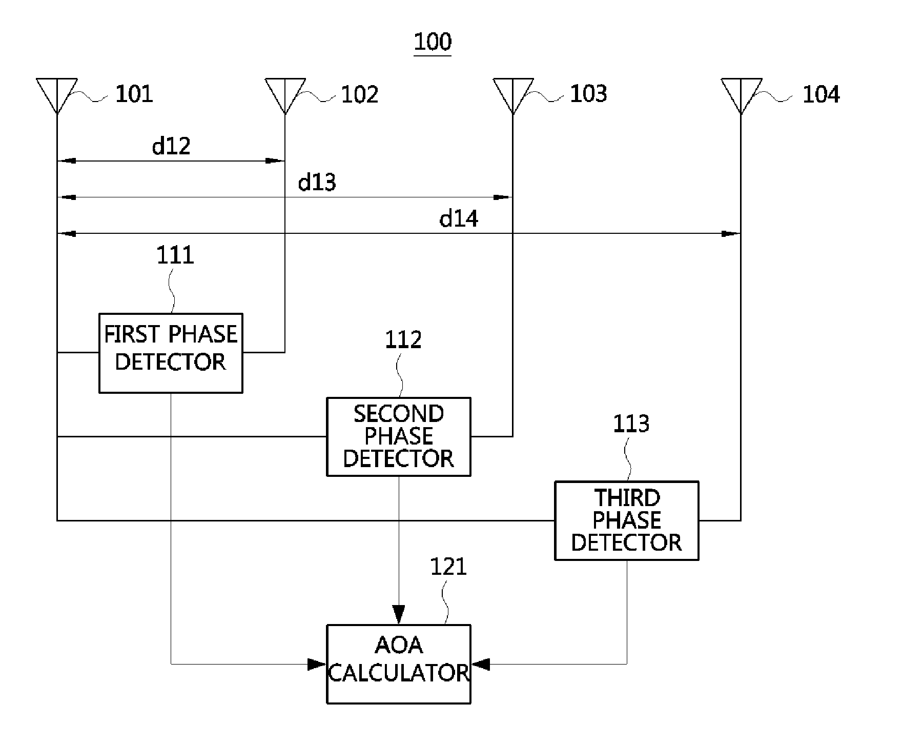
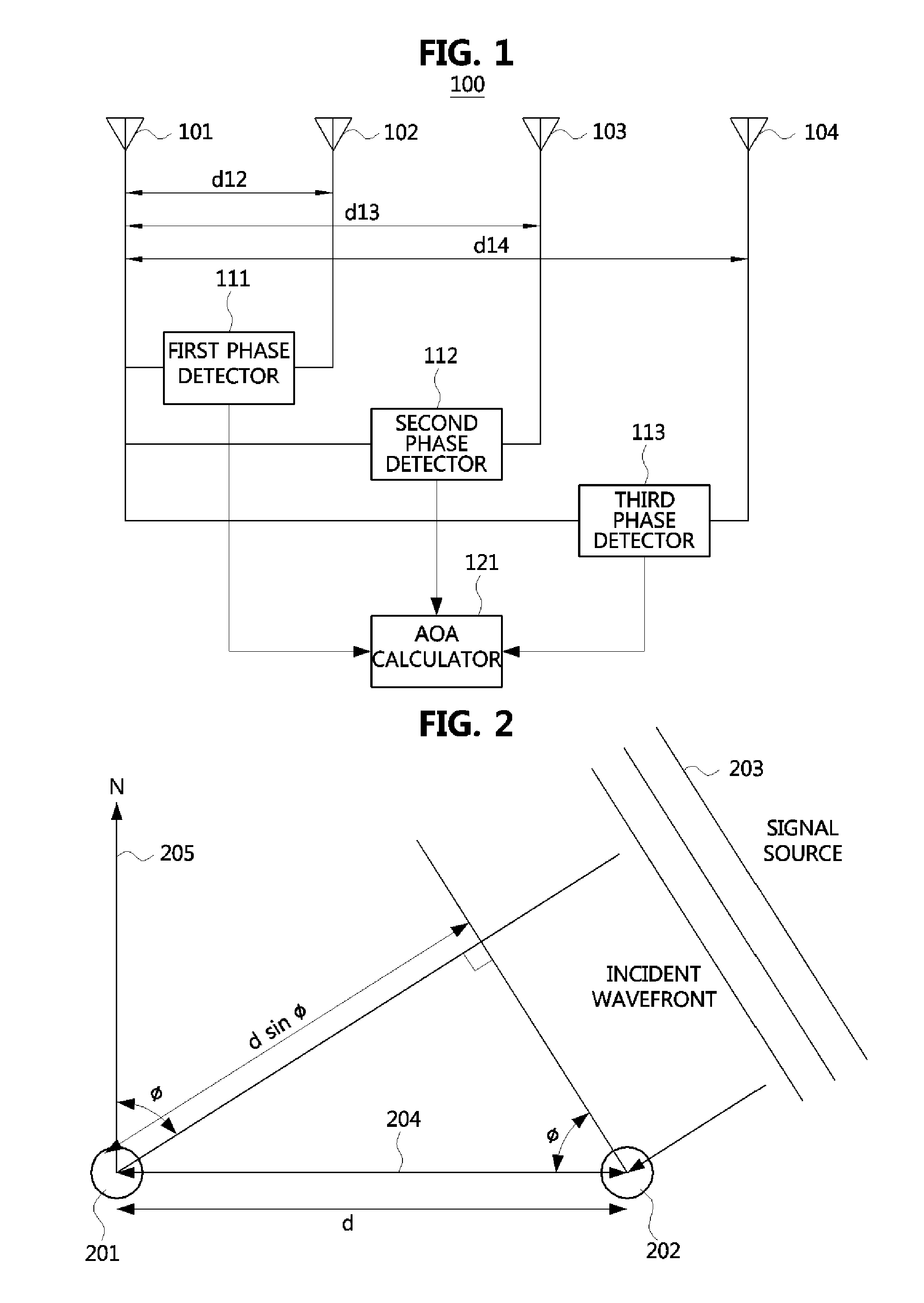
Accordingly, the direction finding apparatus 100 has a complicated configuration, and the manufacturing cost of the direction finding apparatus 100 increases since a plurality of high-cost phase detectors are required.
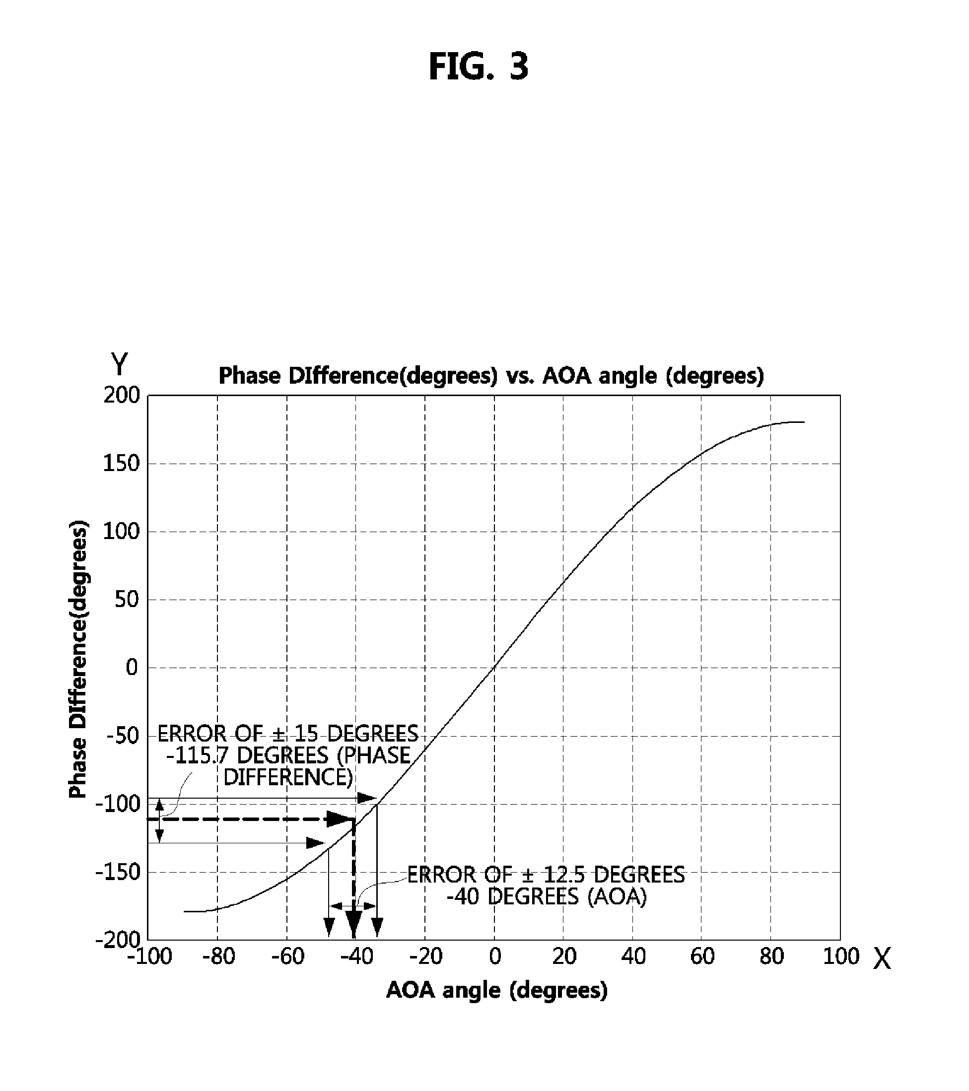
Meanwhile, if two antennas and a single phase detector are used to solve the problem, the error of an AOA increases as the absolute value of the AOA approaches 90 degrees.

Method used


Image

  • Apparatus and method for finding the direction of signal source
  • Apparatus and method for finding the direction of signal source
  • Apparatus and method for finding the direction of signal source

Examples


Embodiment Construction

[0049]Example embodiments of the present invention are disclosed herein. However, specific structural and functional details disclosed herein are merely representative for purposes of describing example embodiments of the present invention; that is, example embodiments of the present invention may be embodied in many alternate forms and should not be construed as limited to example embodiments of the present invention set forth herein.

[0050]Accordingly, while the invention is susceptible to various modifications and alternative forms, specific embodiments thereof are shown by way of example in the drawings and will herein be described in detail. It should be understood, however, that there is no intent to limit the invention to the particular forms disclosed, but on the contrary, the invention is to cover all modifications, equivalents, and alternatives falling within the spirit and scope of the invention. Like numbers refer to like elements throughout the description of the figures...


PUM


Abstract

The direction finding apparatus includes: a first and second antennas configured to receive radio signals respectively; a travel guide unit mechanically coupled with the first and second antennas and configured to provide a travel path along which the first and second antennas are linearly movable; a driver configured to provide a driving force for linearly moving at least one antenna of the first and second antennas in response to a driving control signal; a driving controller configured to provide the driving control signal, wherein the driving control signal is used to separate the first and second antennas from each other by a predetermined distance; and a direction finding unit configured to calculate an angle of arrival (AOA) of radio signals respectively received through the first and second antennas, based on the phase difference between the radio signals, and the predetermined distance.

Description

CLAIM FOR PRIORITY[0001]This application claims priority to Korean Patent Application No. 10-2012-0039637 filed on Apr. 17, 2012 and No. 10-2013-0027804 Mar. 15, 2013 in the Korean Intellectual Property Office (KIPO), the entire contents of which are hereby incorporated by reference.BACKGROUND[0002]1. Technical Field[0003]Example embodiments of the present invention relate in general to a technique for finding the direction of a signal source, and more specifically, to an apparatus and method for finding the direction of a signal source, capable of accurately finding the direction of a signal source through a simple configuration.[0004]2. Related Art[0005]Lately, a need to actively cope with an increase in the use amount of radio waves due to the popularization of wireless communication systems, various service requirements from wireless communication users, and various deregulation requirements due to the liberalization and internationalization of a communication market is increasi...

Claims


Application Information

Patent Timeline
IPC IPC(8): G01S3/48
CPCG01S3/48
Inventor JOO, IN ONELEE, JEOM HUNLEE, SANG UK
Owner ELECTRONICS & TELECOMM RES INST
Learn More