Multiple-lens retinal imaging device and methods for using device to identify, document, and diagnose eye disease

a retinal imaging and multi-lens technology, applied in the field of eye examination, can solve the problems of affecting the quality of eye examination, the relative positioning of photographs, and the inability of contact retinal imaging systems to provide true wide field images, and the difficulty or inability to view standard-field imaging

Inactive Publication Date: 2013-10-17
BROADSPOT IMAGING
View PDF6 Cites 38 Cited by
  • Summary
  • Abstract
  • Description
  • Claims
  • Application Information

AI Technical Summary

Benefits of technology

[0014]In contrast, embodiments of the present invention take advantage of multiple illumination sources 300 distributed among or between the multiple optical pathways 200. At least one of the illumination sources 300 is not coaxial with any of the multiple optical pathways 200 (and typically none 300 are), so that the captured images 60 are not marred by a central light reflex. Because the multiple captured images 60 are partially overlapping, and the relative positions and angles of the images 60 are known, predictable non-central light reflection artifacts are removed at the time of composite image 61 generation (as long as each area of retina 10 that is masked by a light reflection artifact in one image 60 is imaged without a reflection artifact by another image 60 due to the partial overlapping of the multiple generated images 60). Although there are some variations in ocular structure among patients (such as axial length, corneal curvature, and total refractive error), the approximate position of light reflection artifacts generated when using embodiments of this invention is predictable; thus, the multiple optical imaging pathways 200 and multiple illumination sources 300 can be arranged to place the reflection artifacts in such a way as to ensure that partial image 60 overlap provides at least one clear image 60 of every zone 11 within the larger composite image 61.

Problems solved by technology

Because these images are taken sequentially over a finite amount of time, the relative positioning of the photographs is unpredictable, and fine scale maneuvering to obtain more precisely centered images requires a longer imaging session.
Contact retinal imaging systems do not currently provide true wide field images, where “wide field” is defined as an equator-to-equator view in a single image.
This is a disadvantage of present retinal imaging systems, as wide-field images have advantages compared to standard-field images for diagnosis of some medical conditions or eye 1 diseases.
Vision-threatening retinal pathology is often located in the mid-periphery or far periphery of the retina 10, and may be difficult or impossible to view with standard-field imaging.
Some non-contact retinal imaging systems have been able to achieve wide-field images, but these systems typically produce images with significant optical distortion towards the edges of the field.
Because mid-peripheral or peripheral retinal pathology may be relatively subtle and challenging to detect without high quality images, peripheral image distortion may prevent detection or documentation of vision-threatening pathology.
Even when peripheral pathology can be successfully imaged, peripheral distortion may prevent accurate evaluation of lesion size, dimensions, or other characteristics.

Method used


Image

  • Multiple-lens retinal imaging device and methods for using device to identify, document, and diagnose eye disease
  • Multiple-lens retinal imaging device and methods for using device to identify, document, and diagnose eye disease
  • Multiple-lens retinal imaging device and methods for using device to identify, document, and diagnose eye disease

Examples


Embodiment Construction

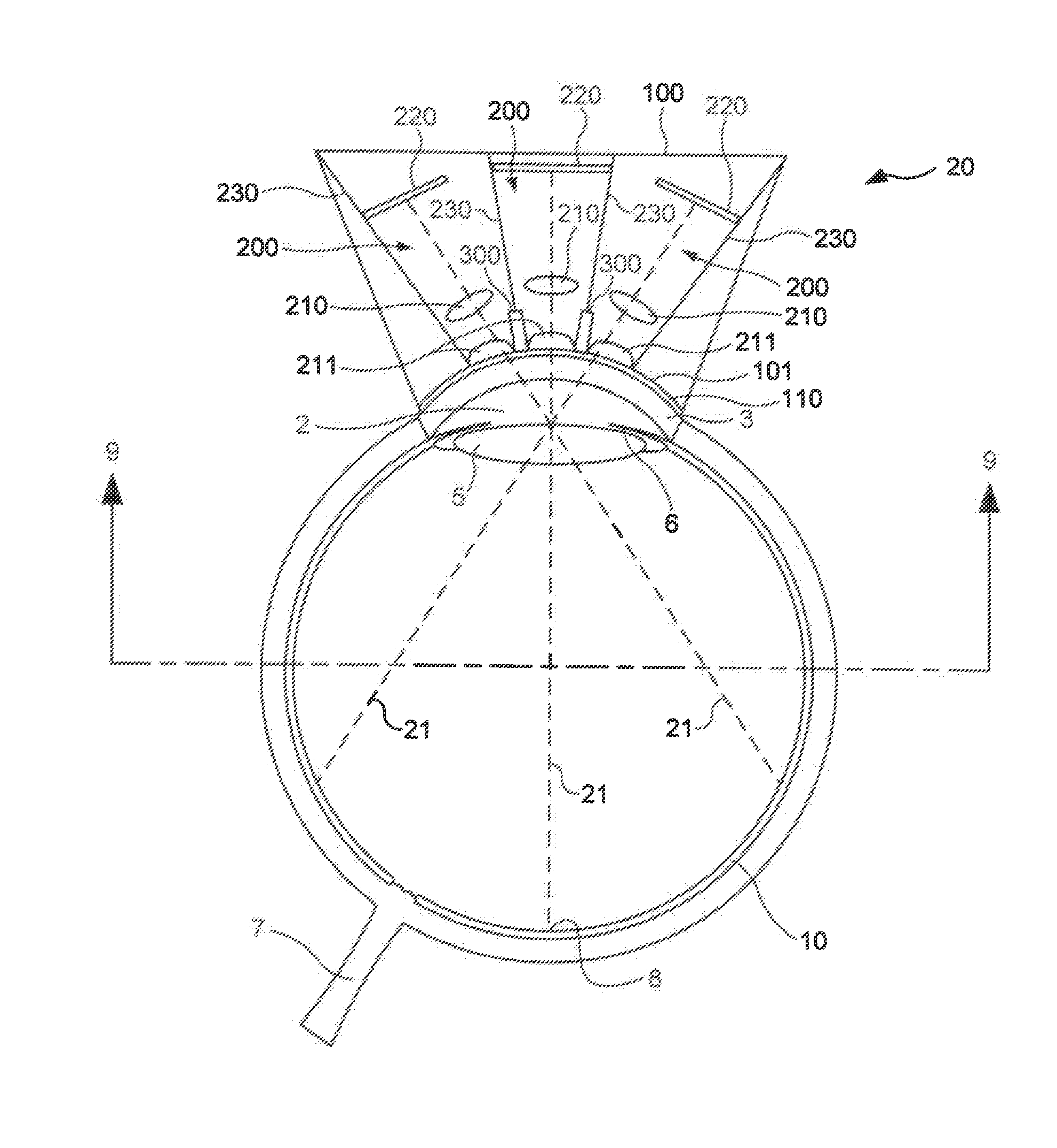
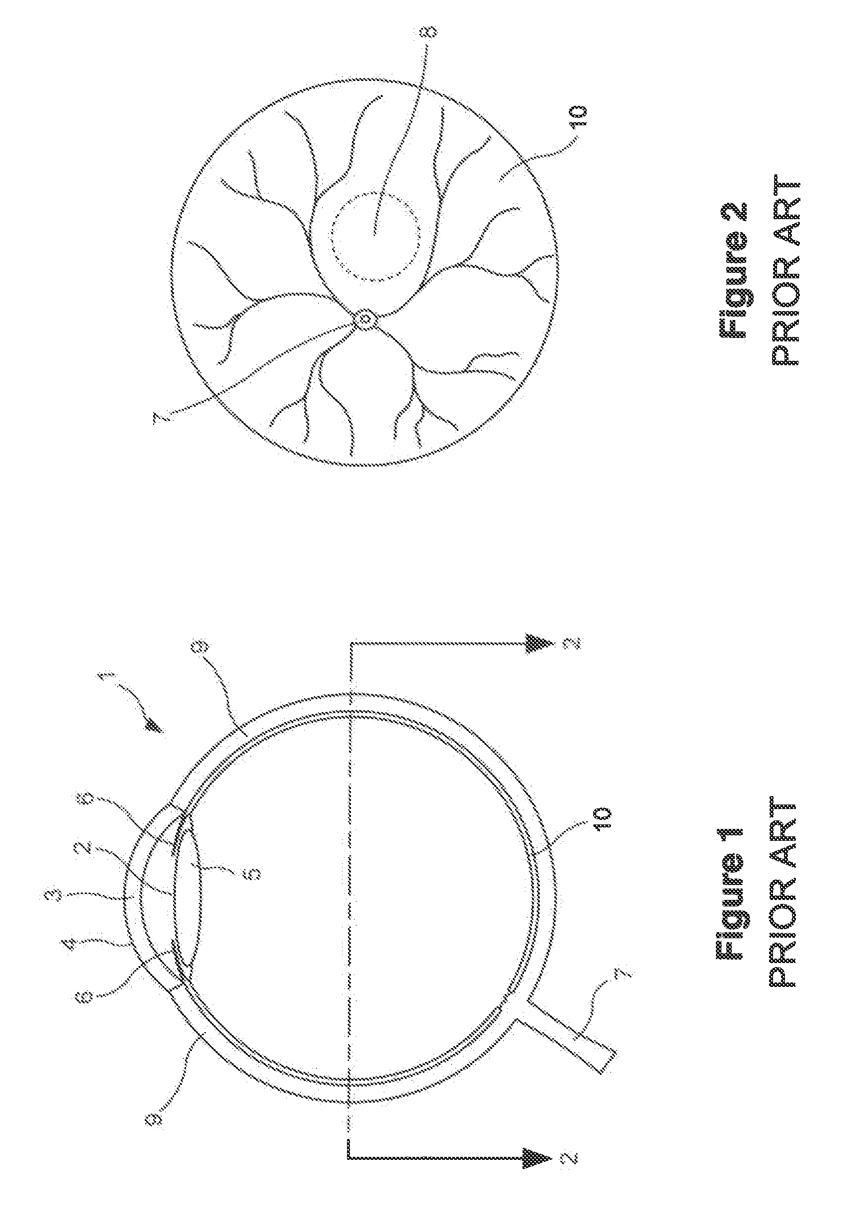
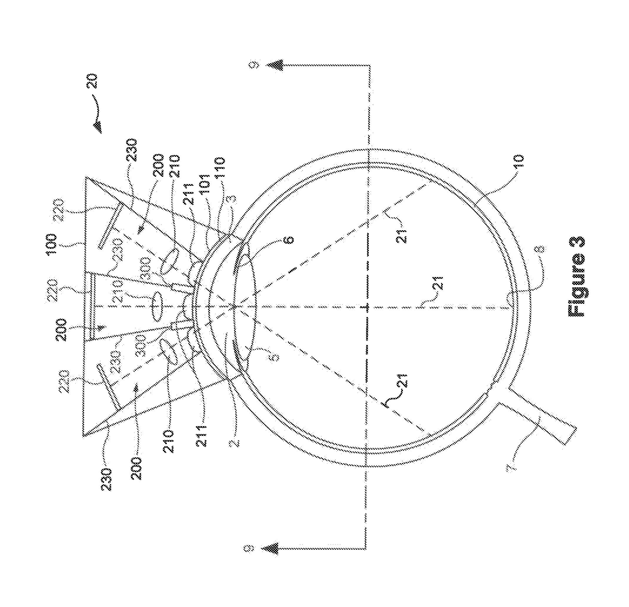
[0036]FIG. 1 illustrates the basic anatomy of the human eye 1 in transverse cross section. FIG. 2 illustrates corresponding landmarks on the retina 10. Structures of the eye 1 that will be referred to in describing one or more embodiments of this invention include: cornea 3, sclera 9, corneoscleral ocular surface 4, which may be placed in physical contact with one surface 101 of chassis 100; iris 6, pupil 2, through which optical paths 21 pass in order to capture images 60 of the retina 10; lens 5, through which optical paths 21 pass in order to capture images 60 of the retina 10; and the retina 10 itself, which is imaged using embodiments of the invention, and which is centered at the macula 8. The cornea 3, sclera 9, and adjacent tissues constitute the ocular surface 4 against which device 20 may be placed in direct contact, with or without a disposable or reusable transparent cover 110.

[0037]The average corneal diameter in a newborn human is approximately 9-10 mm and in an adult ...


PUM


Abstract

A device (20) for use in the screening, documentation, and diagnosis of various diseases of the eye (1). Several images (60) are taken substantially simultaneously, with the images (60) preferably taken in a non-coplanar orientation relative to each other (60). The images (60) represent multiple different zones (11) of the retina (10) taken using different optical imaging pathways (200). Image (60) distortion is minimized, because the individual optical imaging pathways (200) need to account for significantly less differential curvature of the object plane than a wide-field optical pathway that attempts to capture both the central and peripheral retina (10) in a single image. A single composite wide field image (61) can be generated, by merging the overlapping fields of multiple, concurrently captured images (60) taken at different angles.

Description

RELATED PATENT APPLICATIONS [0001]This patent application claims the benefit of commonly-owned U.S. provisional patent applications 61 / 491,898 filed Jun. 1, 2011, and 61 / 501,705 filed Jun. 27, 2011, which two provisional patent applications are hereby incorporated by reference in their entireties into the present patent application.TECHNICAL FIELD [0002]This invention pertains to the field of examining the eye, and obtaining therefrom relevant diagnostic information.BACKGROUND ART [0003]Retinal imaging is commonly used both to screen for retinal diseases and to document findings observed during clinical examination. Retinal photography (sometimes referred to as fundus photography) is presently performed in a variety of ways. In ophthalmology and optometry clinics, fundus photographs made with cooperative adult patients are usually taken with a non-contact digital fundus camera. The camera does not come into direct contact with the eye 1. Fundus cameras may use wide field optics to c...

Claims


Application Information

Patent Timeline
Patent Type & Authority Applications(United States)
IPC IPC(8): A61B3/14
CPCA61B3/14A61B3/12
Inventor RANCHOD, TUSHAR MAHENDRA
Owner BROADSPOT IMAGING
Why Eureka
Try Eureka