[0005]Accordingly, it is an object of the present invention to provide an improved technique for optically checking a part for accurate location and tolerance, and which avoids the drawbacks of the prior art.
[0007]It is a further object to provide a scanning arrangement which can produce scans of higher resolution or at increased scan speeds.
[0008]It is still another object to provide a sheet metal scanner which can accurately measure location and tolerance of holes and openings, even where the part has appreciable thickness.
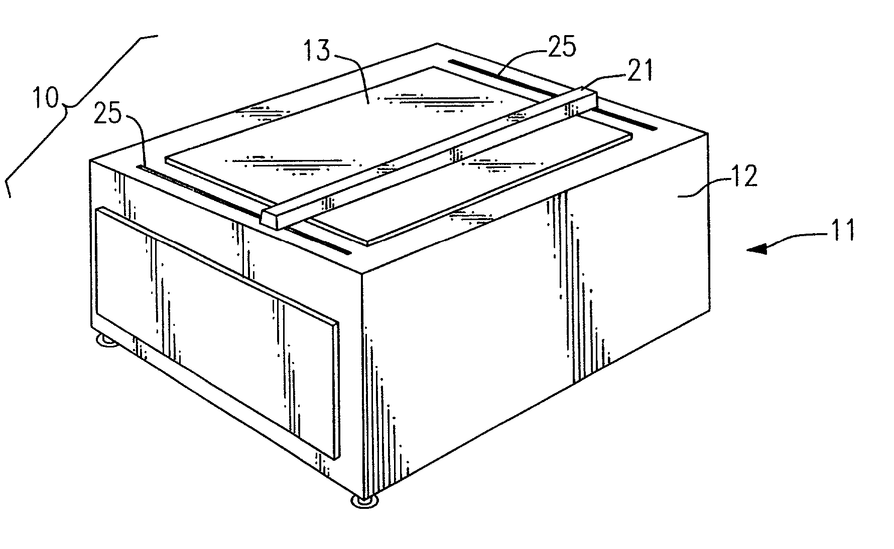
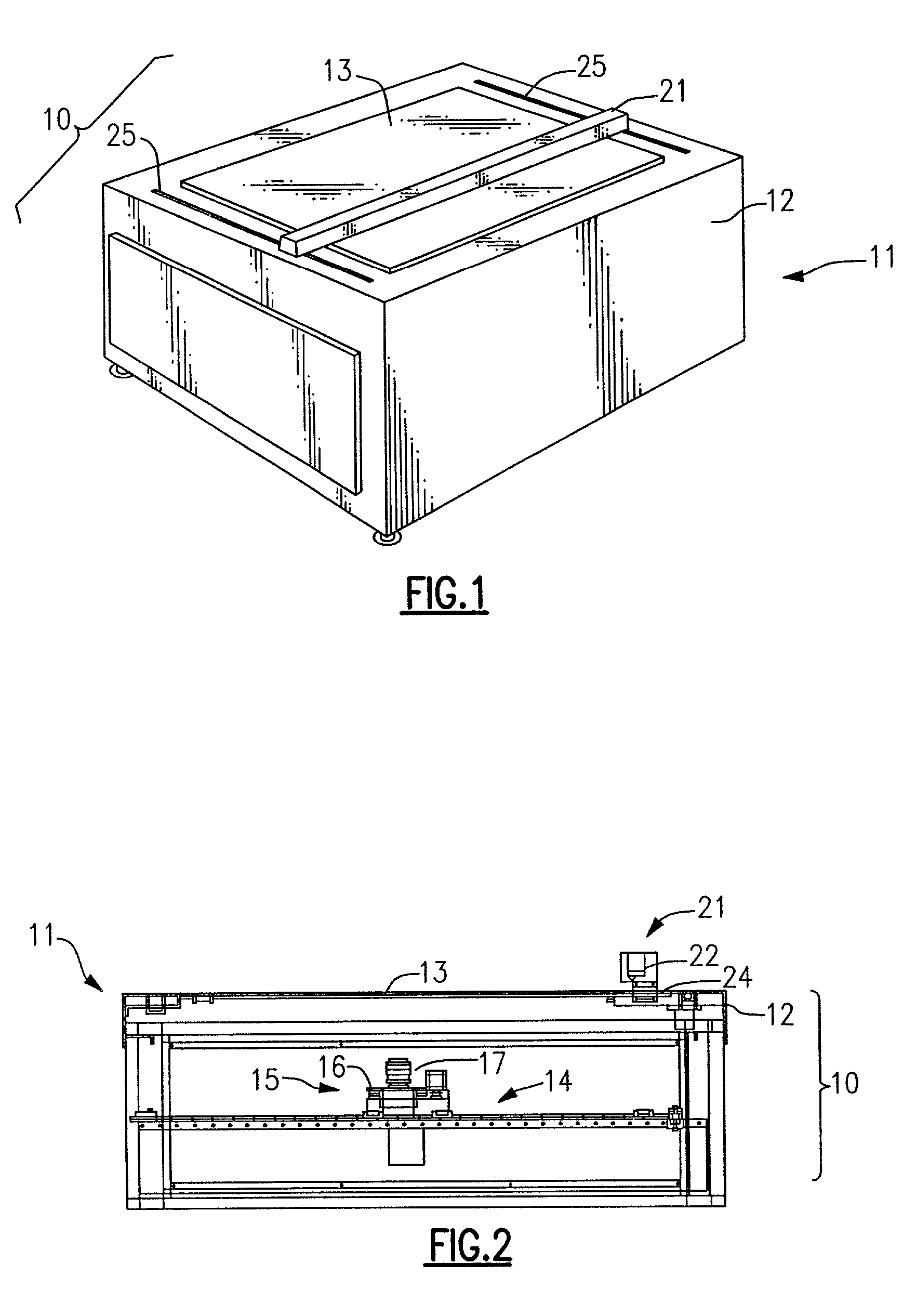
[0010]In accordance with an aspect of the present invention, the scanning apparatus is based on a high-resolution, line-scanning camera mounted onto an X-Y table, located in a lower
assembly having an environmentally sealed housing. On the top of the housing is a transparent support plate, e.g., a sheet of glass 48 inches by 48 inches, upon which the sheet metal part (or blue-print) is placed. The line-scan camera may be precision focused on the top surface of the glass support plate. Preferably, the focus can be adjusted to levels between the surface and an inch above the surface. Located just above the glass support plate is a
light source, i.e., an illuminator, which supplies a line of light across the viewing field. Preferably, the illuminator employs a single high-output fluorescent tube. The illuminator is supported on linear rails and moves in the Y direction, with the tube extending across in the X direction. The drive for the illuminator is separate from the drive for the camera, so the weight and motion of the
light source do not affect motion of the camera, and do not cause camera shake. A
polarizing filter may optionally be placed in front of (i.e., above) the
camera lens to eliminate reflections. In addition to this, inner surfaces of the sealed lower
assembly, as well as the surfaces of the X-Y table, may be coated with a non-reflective paint to eliminate light artifacts. In this arrangement, there are no
moving parts of the apparatus outside the sealed lower portion, except for the illuminator, so there is little chance of
contamination or failure due to factory dust or other
particulates on
moving parts or on the camera
optics. A positioning device allows fine adjustment of the glass support plate to keep the camera in excellent focus for
high resolution scans. Also, damping devices can be incorporated into legs of the unit to accommodate for shocks and vibrations. These may be in the form of rubber-based air or oil-filled dampers, and may be tuned to cancel out specific common vibration frequencies on the
factory floor.
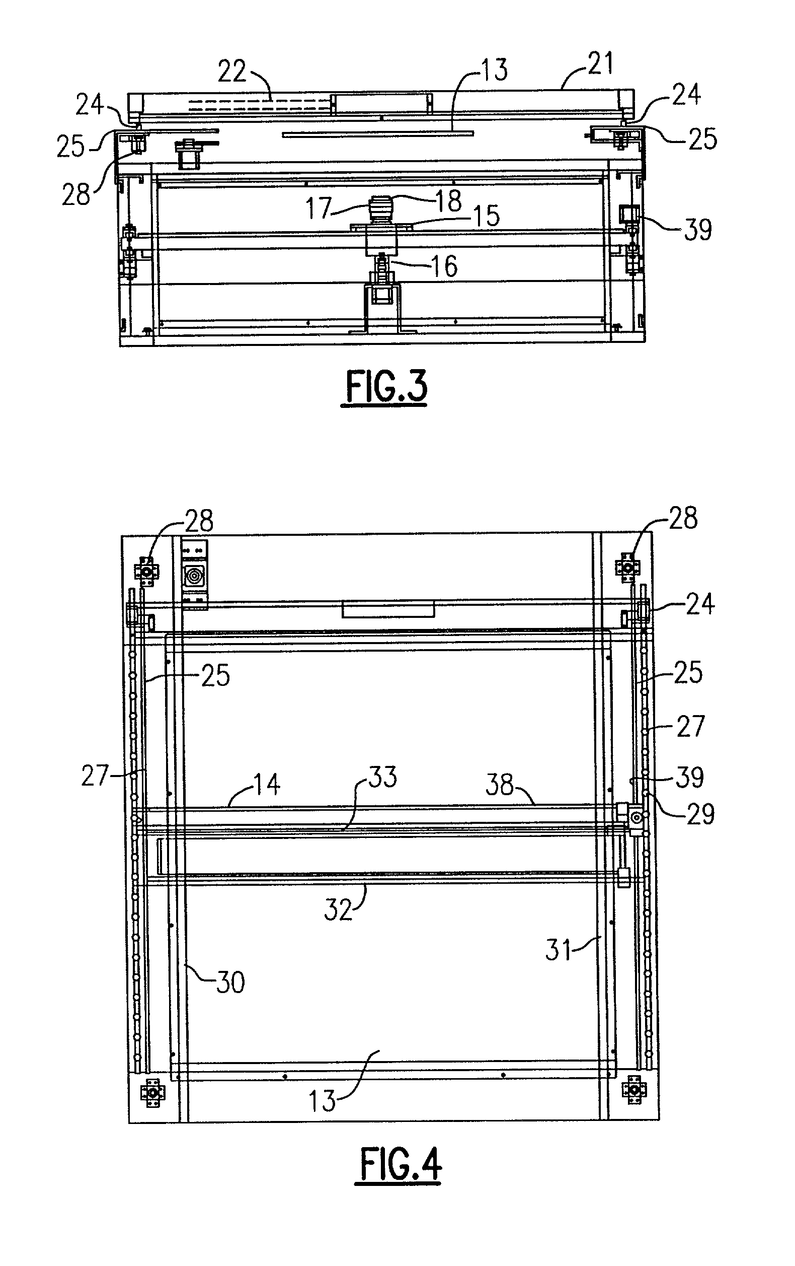
[0011]The X-Y table may be of the type in which there are X- and Y-precision rails, as well as associated lead screws and
stepper motors, or timing belts and pulleys and
stepper motors, plus motor controllers and high-resolution encoders, permitting
high resolution camera movement (e.g., 0.002 inch resolution or better). The size of the scan undertaken by the X-Y table can be controlled to match the size of the part, where the part is smaller than the full 48 by 48 inches, so as to carry out the scan in a reduced time. The camera support on the X- and Y-precision rails has the rails at the level of the camera mounting, so that the camera body sits below the level of the rails. This keeps the center of gravity of the camera below the rails and increases camera stability during movement.
[0012]A
computer control may be used for controlling the camera and the X-Y table.
Software, which may be compatible with Windows NT or Windows 2000, constructs the two-dimensional image of the part from line scans, and may import an existing CAD drawing file for comparison. The CAD file may be in *.DXF or *.DWG format. The
software then compares the scan to the drawing. The
software compares features on the scanned part to specific features on the drawing, and produces a report regarding which items fall within acceptable tolerance, and which do not. The
software may also reverse-engineer a part, creating a *.DXF file or the like based on the scan. The software is also capable of piecing together multiple scans, where an object is greater than 48 inches in length, for example, or may also perform scans of multiple objects placed at the same time on the top surface of the support plate. In the latter case, each object is compared individually with a respective drawing. The software can scan in a high-resolution full phantom for a true calibration over the entire 48-inch-by-48-inch surface. This calibration corrects for slight defects in straightness of the linear rails, sagging of the glass support plate surface, and other factors that can interfere with scan accuracy.

