Method and device for controlling an adjusting device of a motor vehicle

a technology of adjusting device and motor vehicle, which is applied in the direction of electrical control, machine/engine, roof, etc., can solve the problems of damage to the adjusting device or any occupant of the motor vehicle, and achieve the effects of reducing the trapping force, strong loading of the adjusting device and of any object which may be present, and avoiding noise loading

Active Publication Date: 2013-10-24
BROSE FAHRZEUGTEILE GMBH & CO KG
View PDF8 Cites 10 Cited by
  • Summary
  • Abstract
  • Description
  • Claims
  • Application Information

AI Technical Summary

Benefits of technology

[0021]The increasing of the first force to the force setpoint value advantageously takes place in a continuous, in particular linear, fashion. In this way, strong loading of the adjusting device and of the object which may be present is avoided. In addition, the noise loading is low. If the object is an occupant's hand or the like, for example overreactions, resulting from jolting actuation of the adjusting part, are also avoided.
[0022]According to the second variant of the invention, a value for the drive force which is implemented during the normal operating mode is used as a force setpoint value to achieve a f

Problems solved by technology

In particular, the force setpoint value is lower than a legally prescribed limiting value or a v

Method used


Image

  • Method and device for controlling an adjusting device of a motor vehicle
  • Method and device for controlling an adjusting device of a motor vehicle
  • Method and device for controlling an adjusting device of a motor vehicle

Examples


Embodiment Construction

[0038]Corresponding components are provided with the same reference symbols in all the figures.

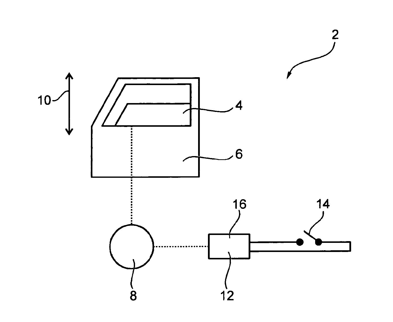
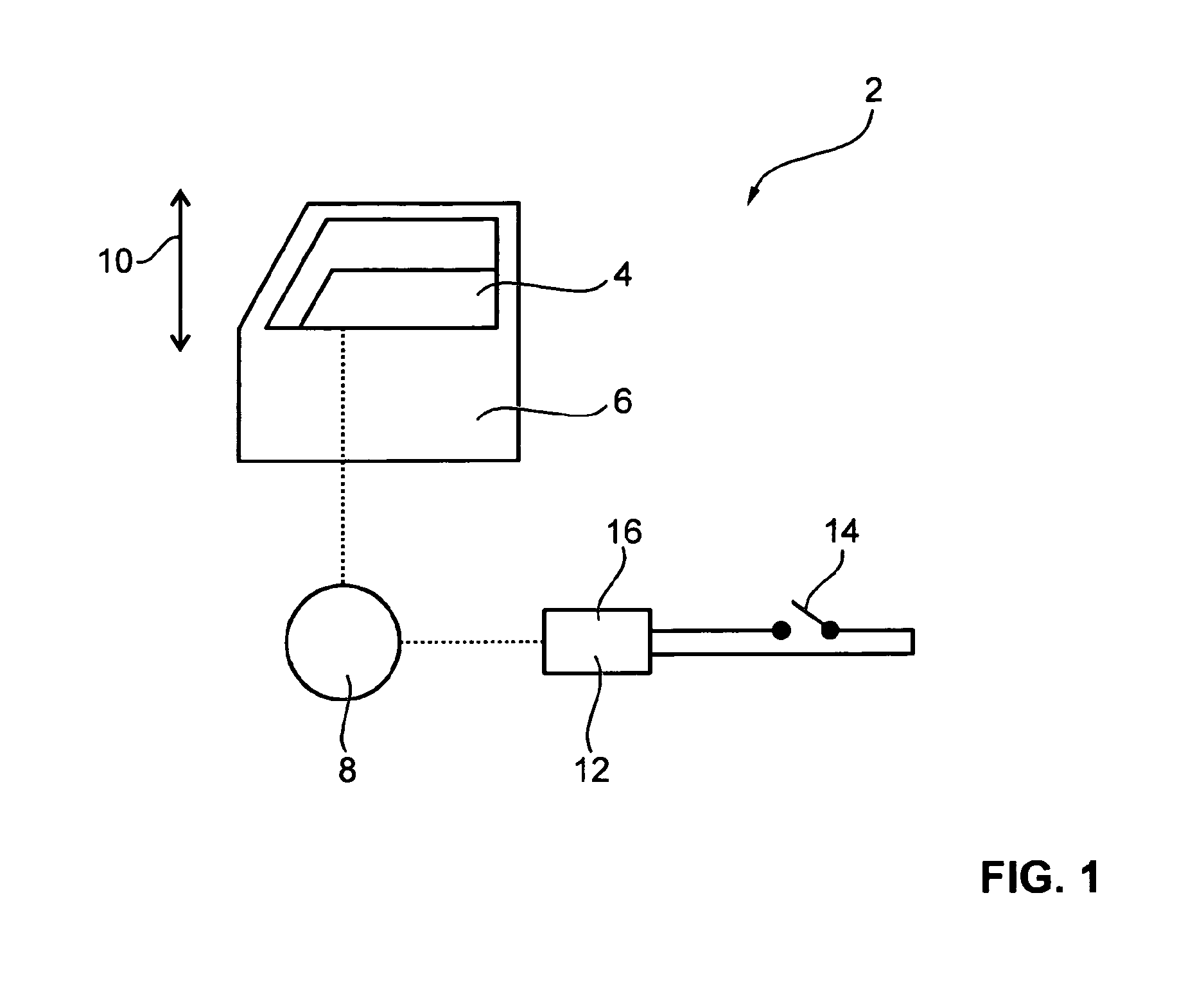
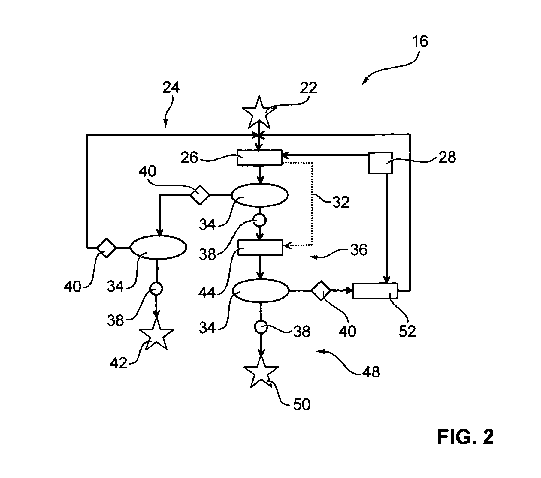
[0039]Referring now to the figures of the drawing in detail and first, particularly, to FIG. 1 thereof, there is shown in schematic form an adjusting device 2 with an adjustment component 4. The adjusting device 2 is, for example, an electric window lifter which is integrated into a door 6 of a motor vehicle. The adjustment component 4 is here a window pane which is moved along an adjustment path 10 by a drive 8. The drive 8 is controlled by a control unit 12 which is actuated by a pushbutton key 14 by an occupant of the motor vehicle. A speed and force adjusting device 16 is located inside the control unit 12.

[0040]The drive 8 is, for example, an electric motor which is operated by pulse width modulation. The electrical energy supplied to the drive 8 is controlled by varying the mark-to-space ratio. In particular, the energy is in a functional relationship with a drive force 18 which move...


PUM


Abstract

In order to control an adjusting device of a motor vehicle, in particular a window lift, having a motor-driven adjusting part, the speed of the drive is controlled to a desired speed value during normal operation at least in a sub-range of an adjustment travel and the driving force is controlled to a desired force value in the event of difficult motion for a first time period. After the first time period has ended, the adjusting part is reversed or the drive is at least stopped in the event of pinching. If the difficult motion is not an event of pinching, the speed of the drive is controlled anew to the desired speed value, wherein the driving force is first reduced to a first force and is increased to the desired force value within a second time period and/or a value realized during normal operation is used as a desired force value for the driving force.

Description

CROSS-REFERENCE TO RELATED APPLICATION[0001]This is a continuation application, under 35 U.S.C. §120, of copending international application No. PCT / EP2011 / 005846, filed Nov. 21, 2011, which designated the United States; this application also claims the priority, under 35 U.S.C. §119, of German patent application No. DE 10 2010 055 650.5, filed Dec. 22, 2010; the prior applications are herewith incorporated by reference in their entireties.BACKGROUND OF THE INVENTIONField of the Invention[0002]The invention relates to a method for controlling an adjusting device of a motor vehicle and an adjusting device operating according to the method.[0003]Published, non-prosecuted German patent application DE 196 15 581 A1 describes a method for actuating electric drives in motor vehicles, in which a working range is selected for an electric motor which drives an assembly such as, for example, a windshield wiper or a window pane of an electric window lifter. Working range is understood here to ...

Claims


Application Information

Patent Timeline
IPC IPC(8): F02D45/00
CPCF02D45/00H02H7/0851B62D5/0487B60J7/0573
Inventor KROMER, ALEXKLAUCK, THOMAS
Owner BROSE FAHRZEUGTEILE GMBH & CO KG
Why Eureka
Try Eureka