Auto-ignition internal combustion engine with partial deactivation and method for the operation of an internal combustion engine of said type

a technology of internal combustion engine and partial deactivation, which is applied in the direction of combustion engine, combination engine, electric control, etc., to achieve the effect of not contributing to efficiency losses, reducing specific fuel consumption, and increasing load

Active Publication Date: 2013-10-24
FORD GLOBAL TECH LLC
View PDF8 Cites 19 Cited by
  • Summary
  • Abstract
  • Description
  • Claims
  • Application Information

AI Technical Summary

Benefits of technology

[0014]For example, during part-load operation of the internal combustion engine, that is, at low and if appropriate medium loads, at least one cylinder of one group is deactivated while at least one cylinder of at least one other group continues to be operated. If a predefinable load is undershot, a partial deactivation thus takes place, as a result of which load demand on at least one cylinder which remains in operation is increased, leading to advantages already described above. The power demand on the cylinders which are still in operation during the partial deactivation increases, such that said cylinders are operated at higher loads with a lower specific fuel consumption. Furthermore, a deactivated cylinder does not generate any wall heat losses, and thus does not contribute to efficiency losses as a result of heat transfer into the engine structure.
[0015]Additionally, since efficiency correlates with compression ratio of cylinder, part-load operation of the diesel engine may be further improved by having cylinder groups with different compression ratios.
[0016]In this way, by utilizing multiple cylinder groups with different efficiencies, part-load operation of auto-ignition internal combustion engine may be improved.

Problems solved by technology

Furthermore, a deactivated cylinder does not generate any wall heat losses, and thus does not contribute to efficiency losses as a result of heat transfer into the engine structure.

Method used


Image

  • Auto-ignition internal combustion engine with partial deactivation and method for the operation of an internal combustion engine of said type
  • Auto-ignition internal combustion engine with partial deactivation and method for the operation of an internal combustion engine of said type
  • Auto-ignition internal combustion engine with partial deactivation and method for the operation of an internal combustion engine of said type

Examples


Embodiment Construction

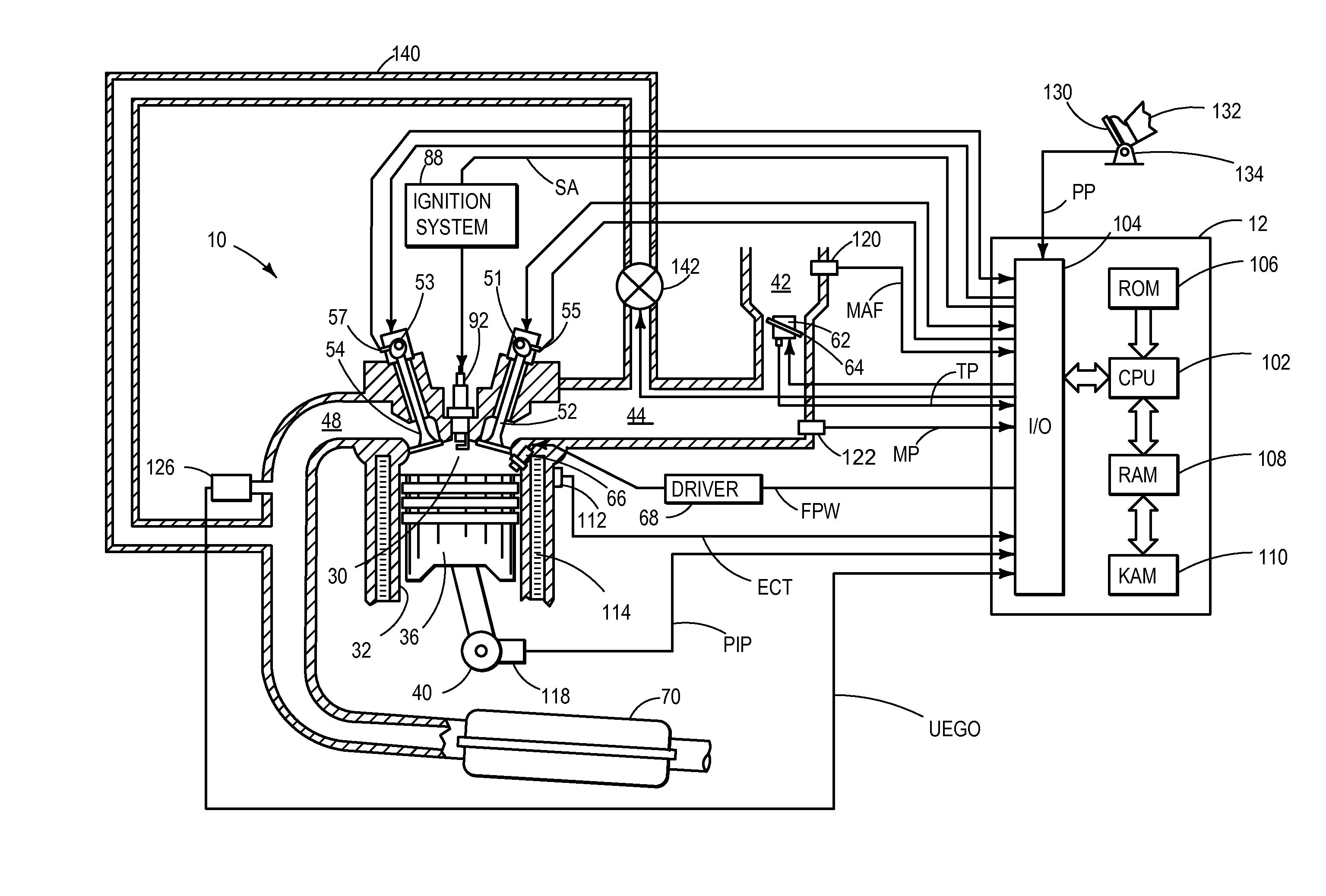
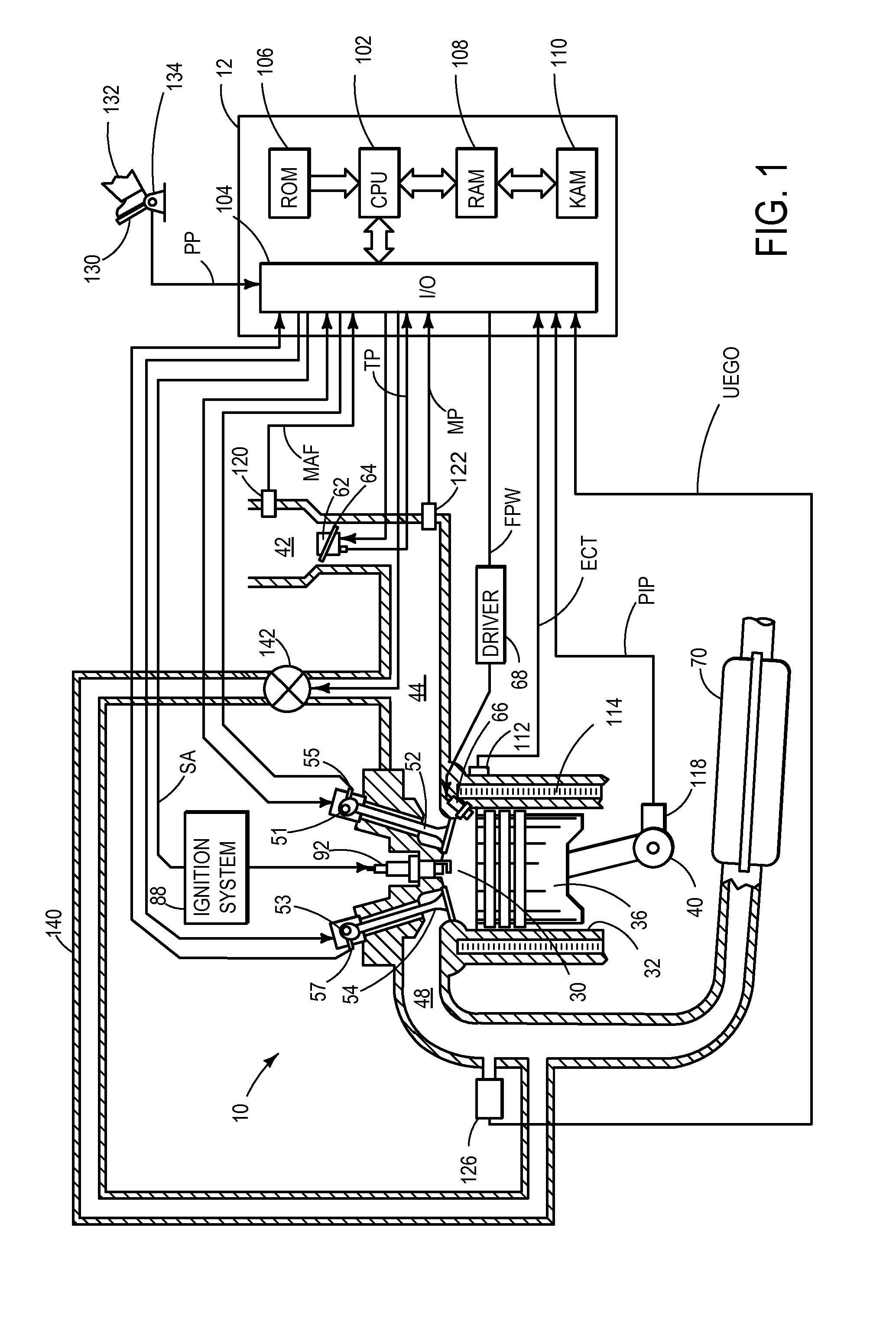
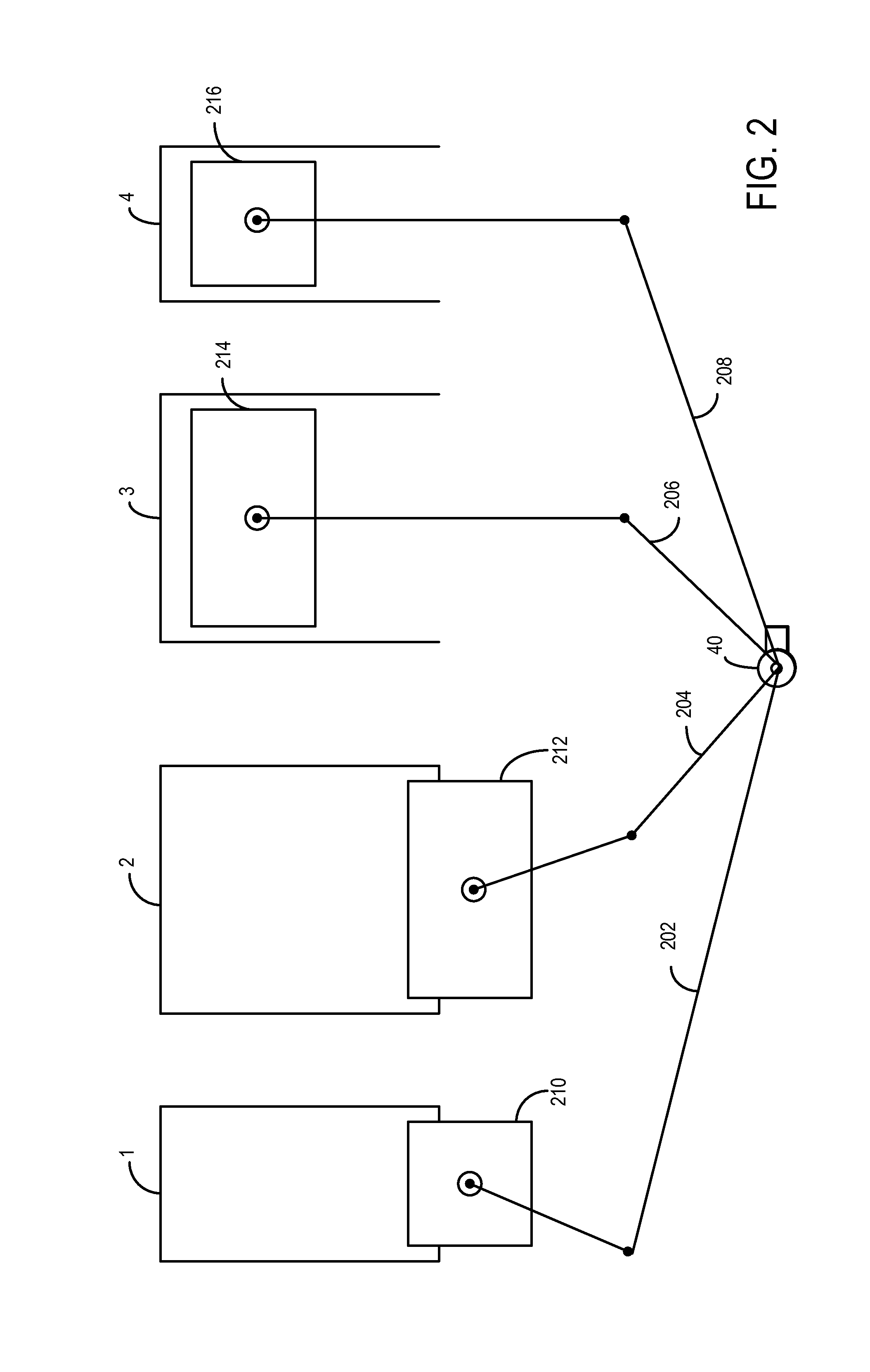
[0023]Methods and systems are provided for operation of an internal combustion engine, such as engine system of FIG. 1. The internal combustion engine of FIG. 1 may be configured as described at FIG. 2. Operation of the internal combustion engine may be optimized with regard to fuel consumption, according to routines described in flow charts of FIGS. 3 and 4.

[0024]Referring to FIG. 1, internal combustion engine 10 comprises of a plurality of cylinders, one cylinder of which is shown in FIG. 1. Engine 10 may be controlled at least partially by a control system including controller 12 and by input from a vehicle operator 132 via an input device 130. In this example, input device 130 includes an accelerator pedal and a pedal position sensor 134 for generating a proportional pedal position signal PP. Combustion chamber (i.e., cylinder) 30 of engine 10 may include combustion chamber walls 32 with piston 36 positioned therein. Piston 36 may be coupled to crankshaft 40 so that reciprocatin...


PUM


Abstract

Methods and systems are provided for optimizing the operation of a multi-cylinder auto-ignition internal combustion engine. By configuring the cylinders in multiple groups based on compression ratios, and operating the cylinders in a load-dependent manner, fuel consumption may be optimized.

Description

CROSS REFERENCE TO RELATED APPLICATIONS[0001]The present application claims priority to European Patent Application No. 12165339.8, filed on Apr. 24, 2012 the entire contents of which are hereby incorporated by reference for all purposes.FIELD[0002]The present disclosure relates to systems and methods for optimized operation of auto-ignition internal combustion engine with partial deactivation.BACKGROUND AND SUMMARY[0003]In the development of internal combustion engines, it is a basic aim to minimize fuel consumption, wherein improved overall efficiency is at the focus of the efforts being made.[0004]Even though diesel engines, that is, one example of auto-ignition internal combustion engines, owing to the quality regulation which they use, have higher efficiency, that is, lower fuel consumption, than Otto-cycle engines in which the load is set by means of quantity regulation by means of the charging of the cylinders with fresh mixture, there is potential for improvement, and a dema...

Claims


Application Information

Patent Timeline
Patent Type & Authority Applications(United States)
IPC IPC(8): F02D17/02
CPCF02D17/02F02B73/00F02D15/00F02D41/0087Y02T10/12
Inventor SPRINGER, MORITZ KLAUSBREUER, ALBERTLORENZ, THOMASRUHLAND, HELMUT HANSLINSEL, JAN
Owner FORD GLOBAL TECH LLC
Why Eureka
Try Eureka