
Heat exchanger

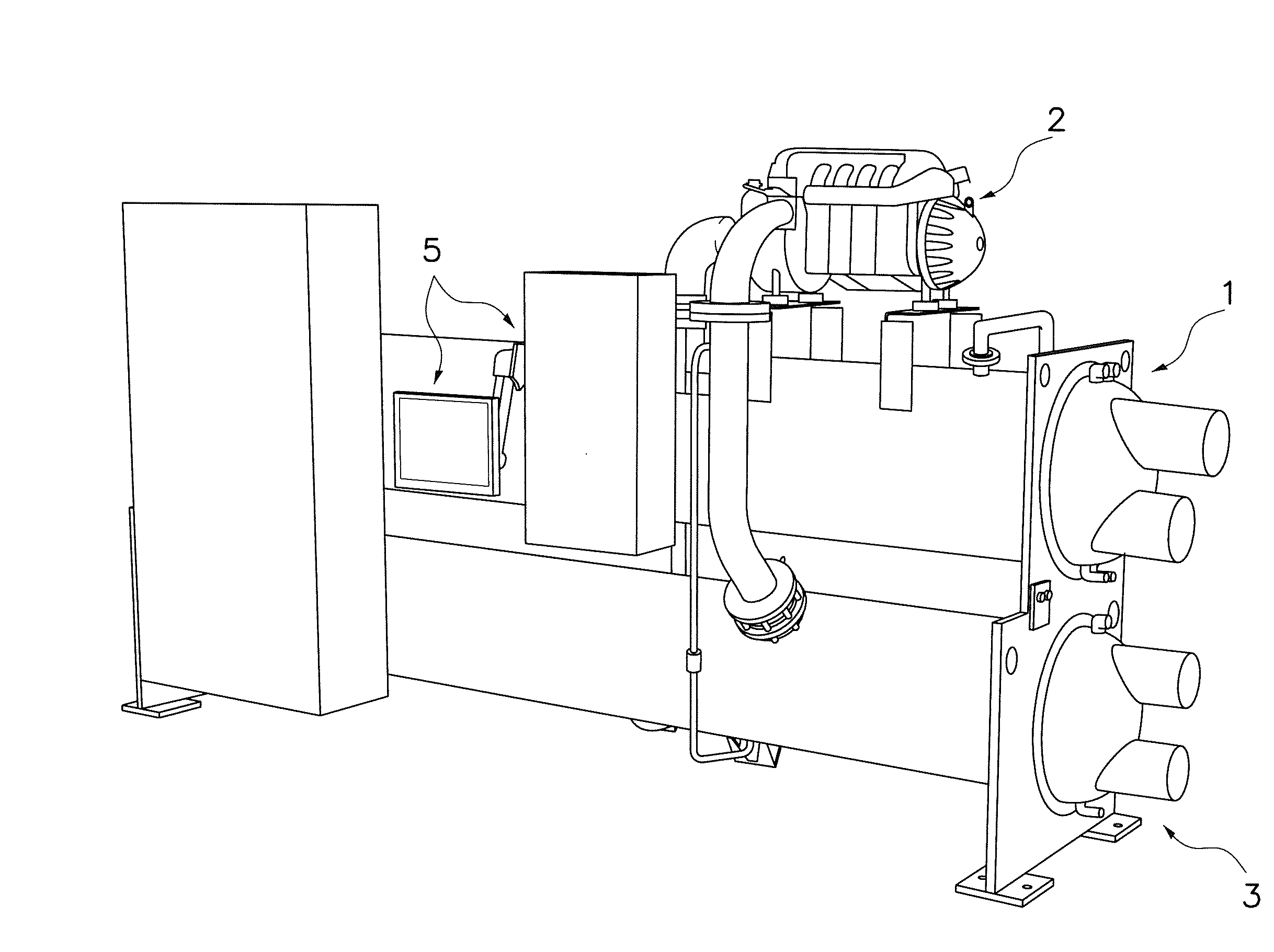
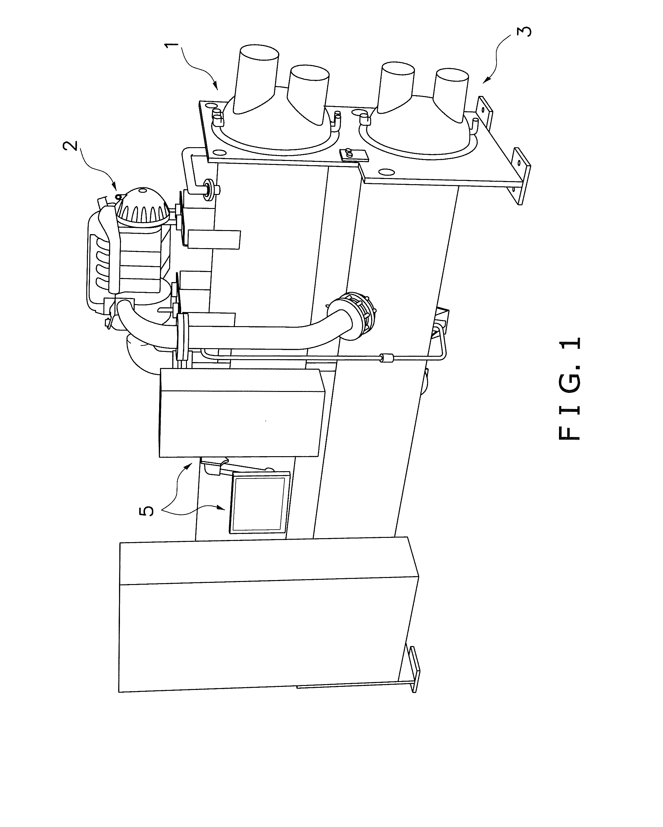
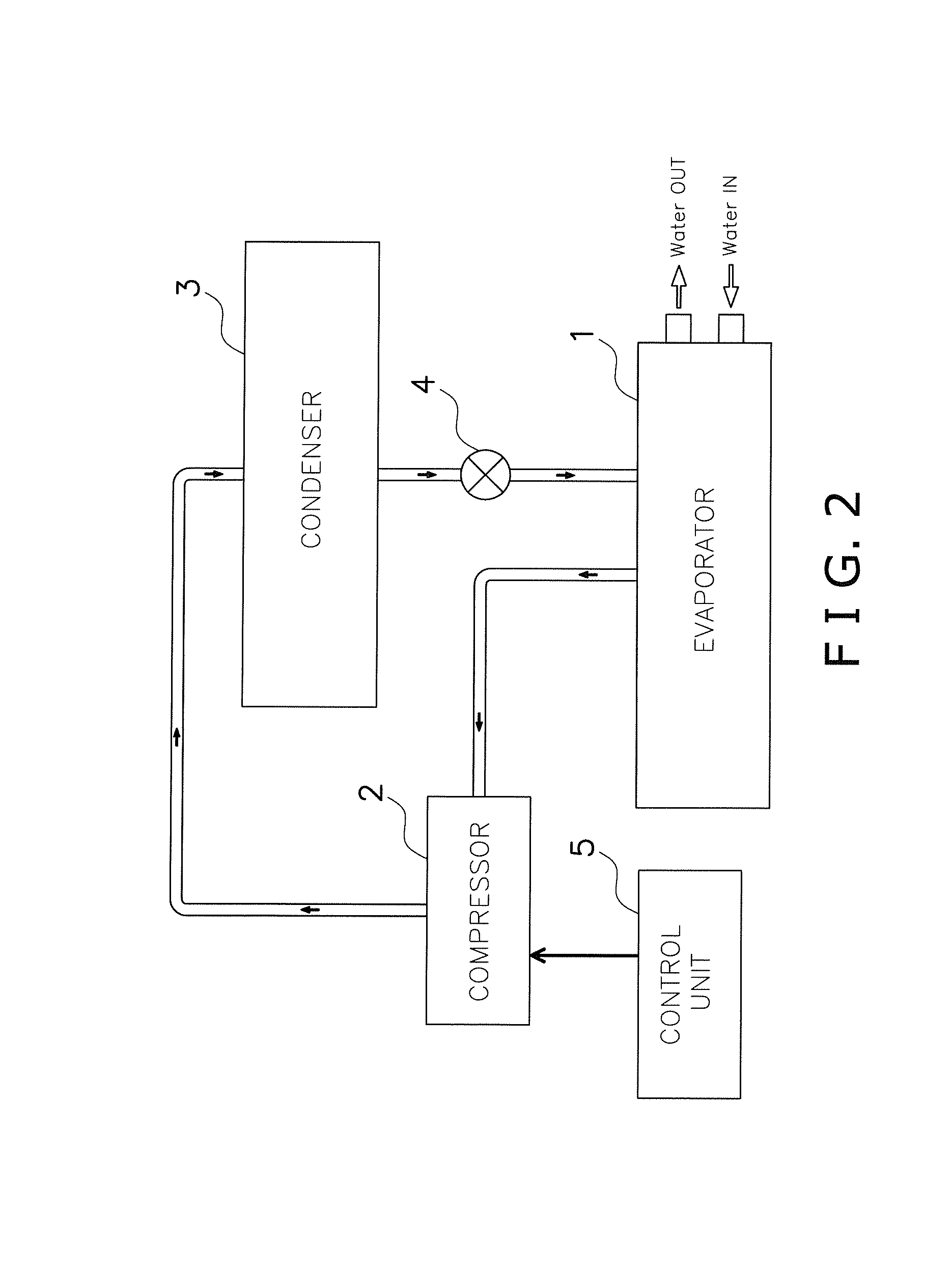
a technology of heat exchanger and heat exchanger body, which is applied in the direction of refrigeration components, stationary conduit assemblies, refrigeration machines, etc., can solve the problems of increasing the manufacturing cost increasing the structure complexity of the spray distribution system, and increasing the pressure loss of the distribution system, so as to reduce the amount of refrigerant charge, the evaporator can be maintained without significant degradation, and the demand for better performance during part-load condition and rated load condition has increased.

Active Publication Date: 2013-10-24
DAIKIN IND LTD
View PDF1 Cites 38 Cited by
  • Summary
  • Abstract
  • Description
  • Claims
  • Application Information

AI Technical Summary

Benefits of technology

The present invention aims to provide a heat exchanger with a refrigerant distribution system that can efficiently distribute refrigerant over a heat transfer unit, even at part-load conditions. The system ensures uniform distribution of refrigerant, even if the evaporator is not perfectly level, which can improve the performance of the heat exchanger. Additionally, by reducing the amount of refrigerant charge, the system saves energy and promotes cost-effectiveness.

Problems solved by technology

Therefore, such a distribution system requires a relatively large amount of refrigerant charge.
On the other hand, in the distribution system utilizing the spray tree distribution system disclosed in U.S. Pat. No. 5,588,596, the number and size of spray orifices formed in the distribution tubes need to be precisely controlled in view of a distribution flow amount and pressure loss due to the pipe length of the distribution tubes, and thus, structural complexity of the spray distribution system increases manufacturing cost.
Moreover, the use of distribution tubes causes a higher pressure loss in the distribution system.
Furthermore, distribution of the liquid refrigerant may become uneven due to reduced refrigerant flow rate when the evaporator operates under part-load condition.
However, with the falling film evaporator, when the refrigerant distributed over the tube bundle decreases due to decrease in the circulation amount of the refrigerant, distribution of the refrigerant within the distributor system may become uneven, which could cause formation of dry patches in the tube bundle.
Moreover, the evaporator may not be installed completely level, which could aggravate uneven distribution of the refrigerant over the tube bundle.

Method used


Image

  • Heat exchanger
  • Heat exchanger
  • Heat exchanger

Examples


second embodiment

[0084]Referring now to FIGS. 20 to 27, an evaporator 101 in accordance with a second embodiment will now be explained. In view of the similarity between the first and second embodiments, the parts of the second embodiment that are identical to the parts of the first embodiment will be given the same reference numerals as the parts of the first embodiment. Moreover, the descriptions of the parts of the second embodiment that are identical to the parts of the first embodiment may be omitted for the sake of brevity.

[0085]The evaporator 101 of the second embodiment is basically the same as the evaporator 1 of the first embodiment except that an intermediate tray part 60 is provided between the heat transfer tubes 31 in the supply line group of a tube bundle 130 and the heat transfer tubes 31 in the return line group of the tube bundle 130. The intermediate tray part 60 includes a plurality of discharge apertures 60a through which the liquid refrigerant is discharged downwardly. The disc...


PUM


Abstract

A heat exchanger includes a shell, a refrigerant distribution assembly and a heat transferring unit. The refrigerant distribution assembly includes a first tray part and second tray parts. The first tray part continuously extends generally parallel to the longitudinal center axis of the shell to receive a refrigerant that enters the shell. The second tray parts are disposed below the first tray part to receive the refrigerant discharged from first discharge apertures such that the refrigerant accumulated in the second tray parts does not communicate between the second tray parts. The second tray parts are aligned along a direction generally parallel to the longitudinal center axis of the shell. The heat transferring unit is disposed below the second tray parts so that the refrigerant discharged from second discharge apertures of the second tray parts is supplied to the heat transferring unit.

Description

BACKGROUND OF THE INVENTION[0001]1. Field of the Invention[0002]This invention generally relates to a heat exchanger adapted to be used in a vapor compression system. More specifically, this invention relates to a heat exchanger including a refrigerant distributor having a first tray part and a plurality of second tray parts.[0003]2. Background Information[0004]Vapor compression refrigeration has been the most commonly used method for air-conditioning of large buildings or the like. Conventional vapor compression refrigeration systems are typically provided with an evaporator, which is a heat exchanger that allows the refrigerant to evaporate from liquid to vapor while absorbing heat from liquid to be cooled passing through the evaporator. One type of evaporator includes a tube bundle having a plurality of horizontally extending heat transfer tubes through which the liquid to be cooled is circulated, and the tube bundle is housed inside a cylindrical shell. There are several known m...

Claims


Application Information

Patent Timeline
IPC IPC(8): F28D7/00
CPCF25B39/02F25B2339/0242F25B2341/0012F28D3/02F28D3/04F28D5/02
Inventor NUMATA, MITSUHARUKASAI, KAZUSHIGE
Owner DAIKIN IND LTD
Learn More