
Microscope system having a dynamic holographic image reproduction unit

Inactive Publication Date: 2013-10-24
LEICA MICROSYSTEMS (SCHWEIZ) AG
View PDF0 Cites 2 Cited by
  • Summary
  • Abstract
  • Description
  • Claims
  • Application Information

AI Technical Summary

Benefits of technology

The present invention proposes to equip a microscope system, particularly a surgical microscope system, with an image reproduction unit that uses a photorefractive polymer to create a three-dimensional image display. This technology allows for the dynamic holographic reproduction of three-dimensional object image information through the use of a photorefractive polymer that can be reversibly recorded and has high image persistence. The image reproduction unit can be located remotely from the microscope system, for example in a sterile area or at a distance from the operating table. The use of a photorefractive polymer also allows for slower image refresh frequencies and greater image depth reproduction compared to conventional holographic technologies. Overall, this invention offers the advantages of holography while also utilizing the benefits of static holograms and dynamic holograms.

Problems solved by technology

Such systems often cannot, however, ensure a satisfactory spatial impression.
A substantial disadvantage of the previously known digital-optics systems for three-dimensional presentation, conversely, is that the focal plane and the convergence plane are spatially fixed.
The aforesaid systems have therefore not yet always been able to achieve wide acceptance, at least in the sector of surgical microscopy.
In some of the aforesaid systems the sequential presentation of the right / left stereo image pairs for the respectively right and left eye of the observer additionally proves to be disadvantageous.

Method used


Image

  • Microscope system having a dynamic holographic image reproduction unit
  • Microscope system having a dynamic holographic image reproduction unit
  • Microscope system having a dynamic holographic image reproduction unit

Examples


Embodiment Construction

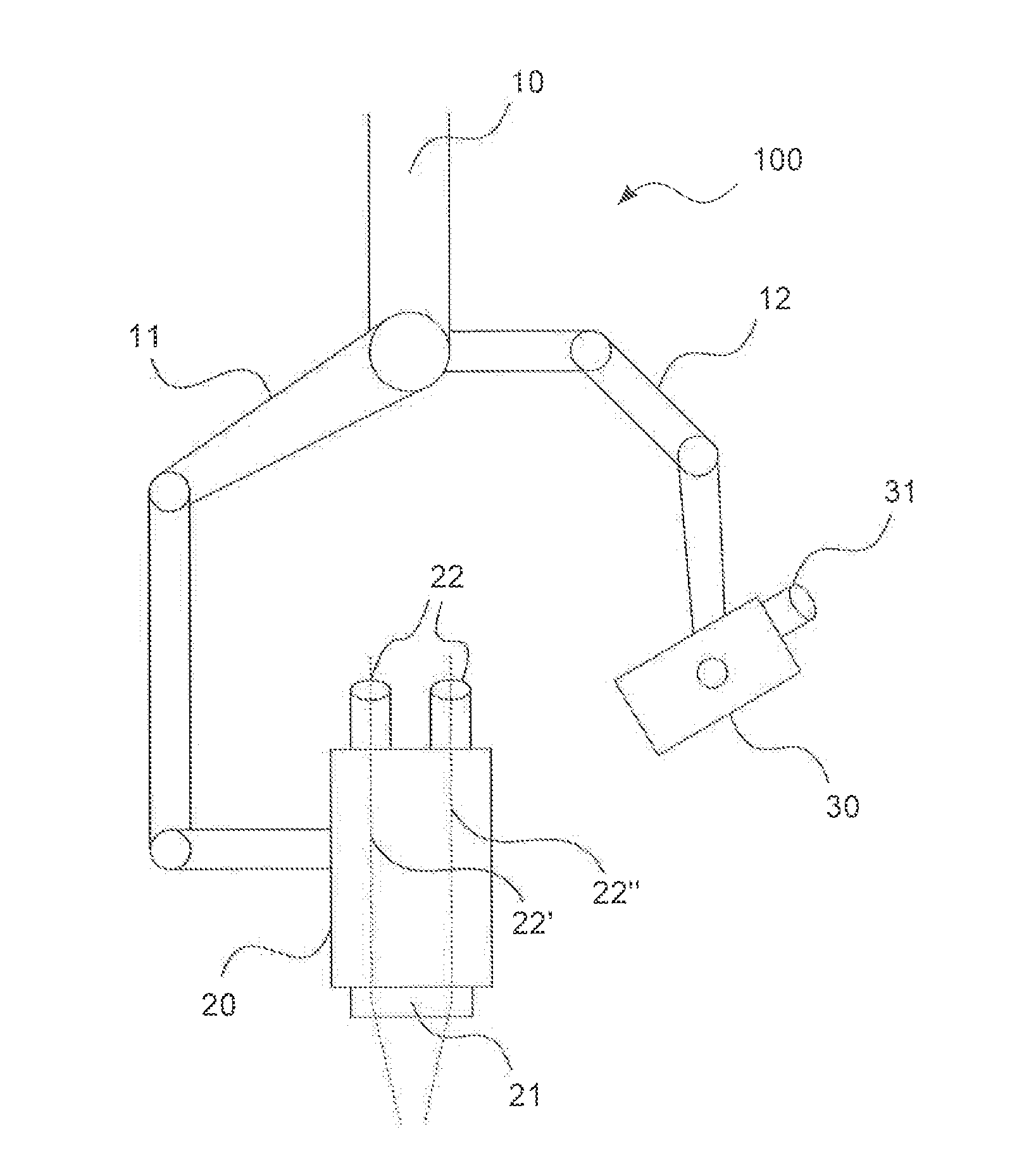
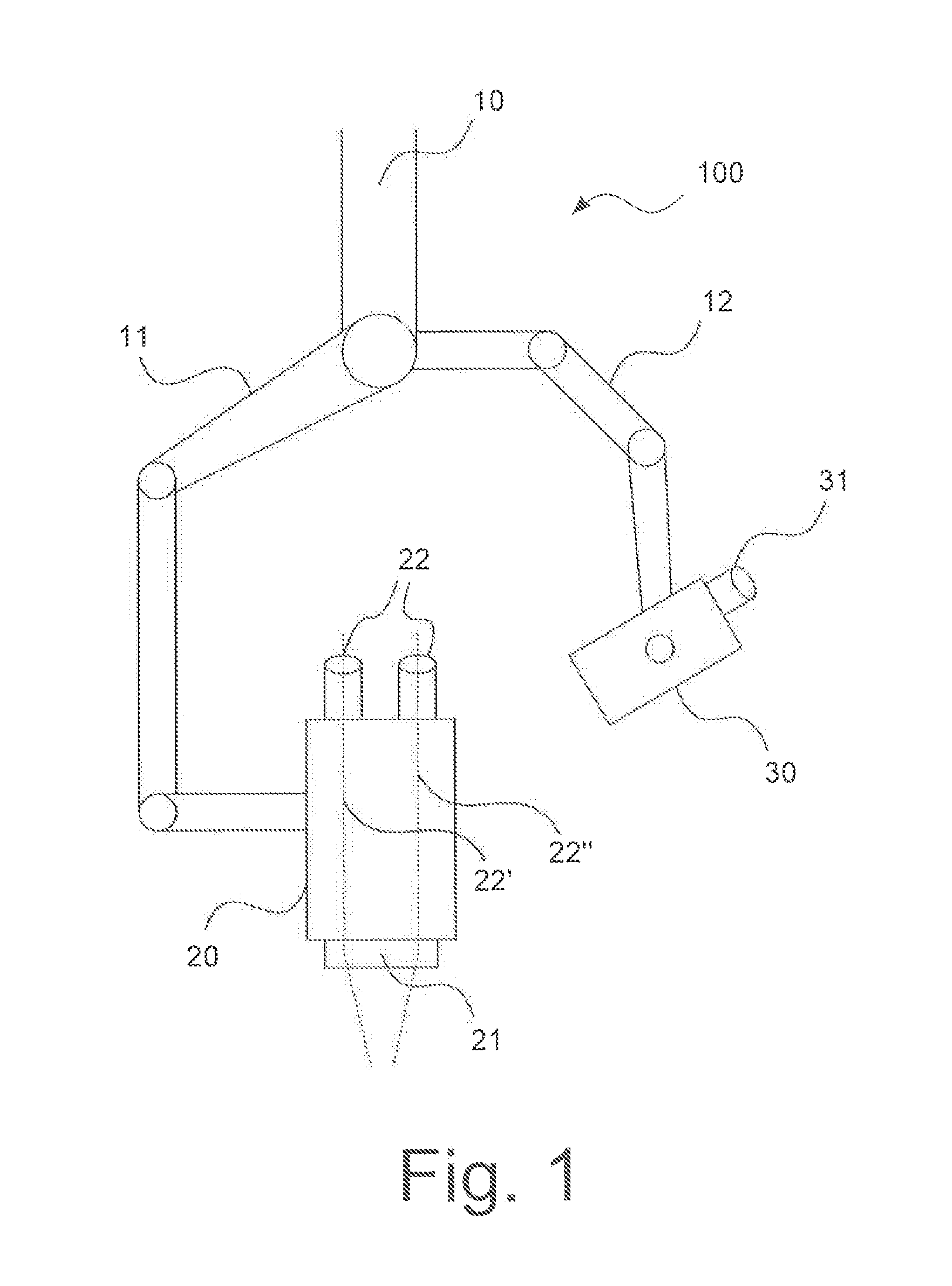
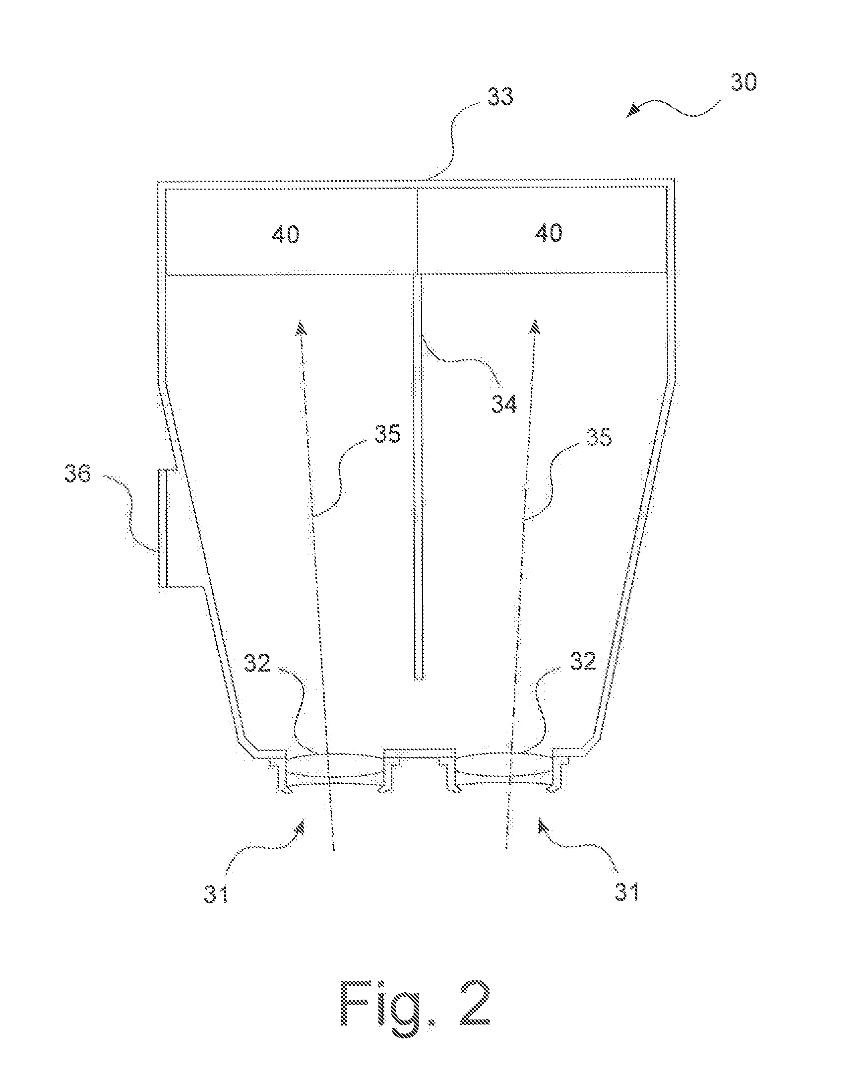
[0056]A microscope system according to a particularly preferred embodiment of the invention is depicted in FIG. 1 and labeled in its entirety as 100. Microscope system 100 is embodied, for example, as a ceiling-mounted surgical microscope system, and is fastened on a carrier arm 10 (not explained in further detail). A binocular stereomicroscope 20 that can possess, for example, an image acquisition unit 21 and eyepieces 22, is attached to a first pivot arm 11. The visual stereoscopic channels are labeled 22′ and 22″. Image acquisition unit 21 is set up to acquire three-dimensional object image data in the form of (conventional) optical and / or digital images and / or in the form of hologram data. It possesses for that purpose, for example, a main objective, a zoom system, an image sensing system, a documentation device, and / or a holographic scanning device. Additional image acquisition devices can be provided. An observer can visually observe, through a pair of eyepieces 22, an object ...


PUM


Abstract

A microscope system (100) is proposed, having at least one image acquisition unit (21) set up to acquire three-dimensional object image information, and having at least one image reproduction unit (30) set up for dynamic holographic reproduction of the three-dimensional object image information, in which system the at least one image reproduction unit (30) encompasses at least one image display unit (40) that comprises a photorefractive polymer (45) and that is set up for dynamic holographic reproduction of three-dimensional object image information by exposing the photorefractive polymer (45) in accordance with the three-dimensional object image information, and wherein the at least one image reproduction unit (30) comprises a viewing port (31), set up for viewing with both eyes of an observer, and an at least partly light-tight housing (33).

Description

CROSS REFERENCE TO RELATED APPLICATIONS[0001]This application claims priority of German patent application number 10 2012 206 594.6 filed Apr. 20, 2012, the entire disclosure of which is incorporated by reference herein.FIELD OF THE INVENTION[0002]The present invention relates to a microscope system, in particular a surgical microscope system, having an image acquisition unit set up to acquire three-dimensional object image information, and having an image reproduction unit set up for dynamic holographic reproduction of the three-dimensional object image information; and to a corresponding image reproduction unit.BACKGROUND OF THE INVENTION[0003]In the field of surgical microscopy in particular, a need exists for investigating movable objects three-dimensionally. Stereomicroscopes, for example, have been known for this purpose for some time.[0004]Overall, however, direct observation of objects with the eye or with corresponding stereomicroscopes will play an increasingly minor role ...

Claims


Application Information

Patent Timeline
IPC IPC(8): G03H1/26
CPCG03H1/268G03H1/26G03H1/265A61B90/20G02B21/0012G02B21/22G02B21/36G03H1/041G03H1/08G03H1/2294G03H2001/0264G03H2001/0413G03H2001/221G03H2210/30G03H2223/19G03H2225/25G03H2260/35G03H2260/54
Inventor SANDER, ULRICH
Owner LEICA MICROSYSTEMS (SCHWEIZ) AG
Learn More