Light emitting systems and related methods

a technology of light-emitting systems and light-emitting systems, applied in the direction of instruments, lighting and heating apparatus, mechanical equipment, etc., can solve the problems of low flux capture effectiveness of prior art light-emitting systems that utilize light guides, difficult to achieve effective flux coupling, etc., to achieve the effect of improving flux coupling and increasing light intensity

Inactive Publication Date: 2013-10-24
LITEIDEAS
View PDF24 Cites 10 Cited by
  • Summary
  • Abstract
  • Description
  • Claims
  • Application Information

AI Technical Summary

Benefits of technology

[0005]It is therefore an object of the present invention to provide a light-emitting system and related method of its fabrication that results in an improved flux coupling and hence increased light intensity in comparison with the light-emitting systems of the prior art.
[0006]It is further object of the present invention to provide a light-emitting system that is compact and easier to fabricate.
[0007]It is yet further object of the present invention to provide a light-emitting system and related method that is characterized by the improved waterproof, shock, and vibration resistant characteristics.
[0014]A method of making an edge-lit thin light-emitting system is disclosed. The method comprises the steps of providing a reflector sheet, disposing a light guide sheet on the reflector sheet, disposing a diffuser lens sheet on the light guide sheet, disposing at least one strip of LED arrays embedded in the optically clear material to a frame such that the non-emissive sides of LEDs are facing the frame; disposing the frame around the perimeter of the sheets such that the at least one strip of LED arrays is aligned with the light guide with the light-emission side of LEDs facing the light guide and the air gap between the LEDs and the light guide is eliminated.
[0016]According to one variant, the method comprises the steps of providing a reflector sheet, disposing a light guide sheet on the reflector sheet, disposing a diffuser lens sheet on the light guide sheet, disposing at least one strip of LED arrays embedded in the optically clear material on the edges of the light guide sheet such that the at least one strip of LED arrays is aligned with the light guide with the light-emission side of LEDs facing the light guide and the air gap between the LEDs and the light guide is eliminated.

Problems solved by technology

The effective flux coupling, however, is very difficult to accomplish.
Consequently, the prior art light-emitting systems that utilize light guides are ineffective because a high percentage of the flux from LEDs is lost before entering the light guide.
This low flux capture effectiveness of the prior art light-emitting systems is inter alia due to the air gap present between the LED and the light guide.

Method used


Image

  • Light emitting systems and related methods
  • Light emitting systems and related methods
  • Light emitting systems and related methods

Examples


Embodiment Construction

[0005]It is therefore an object of the present invention to provide a light-emitting system and related method of its fabrication that results in an improved flux coupling and hence increased light intensity in comparison with the light-emitting systems of the prior art.

[0006]It is further object of the present invention to provide a light-emitting system that is compact and easier to fabricate.

[0007]It is yet further object of the present invention to provide a light-emitting system and related method that is characterized by the improved waterproof, shock, and vibration resistant characteristics.

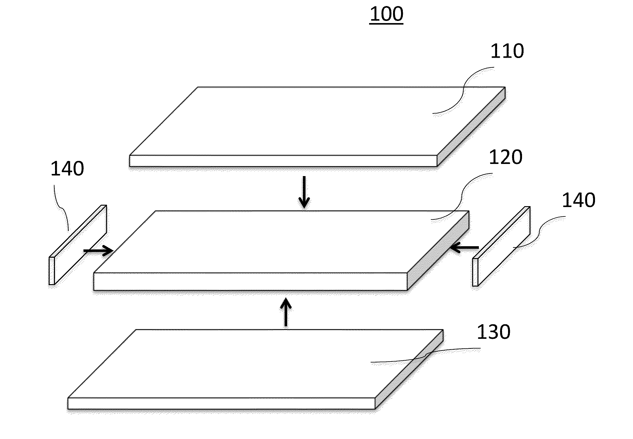
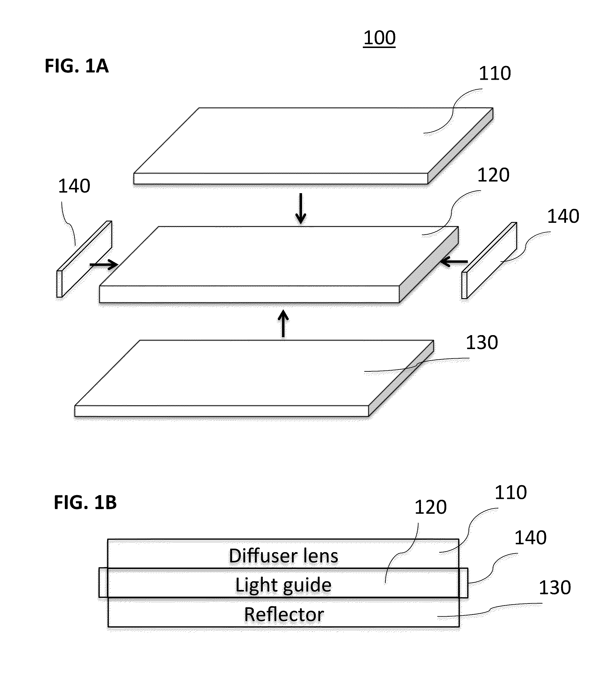
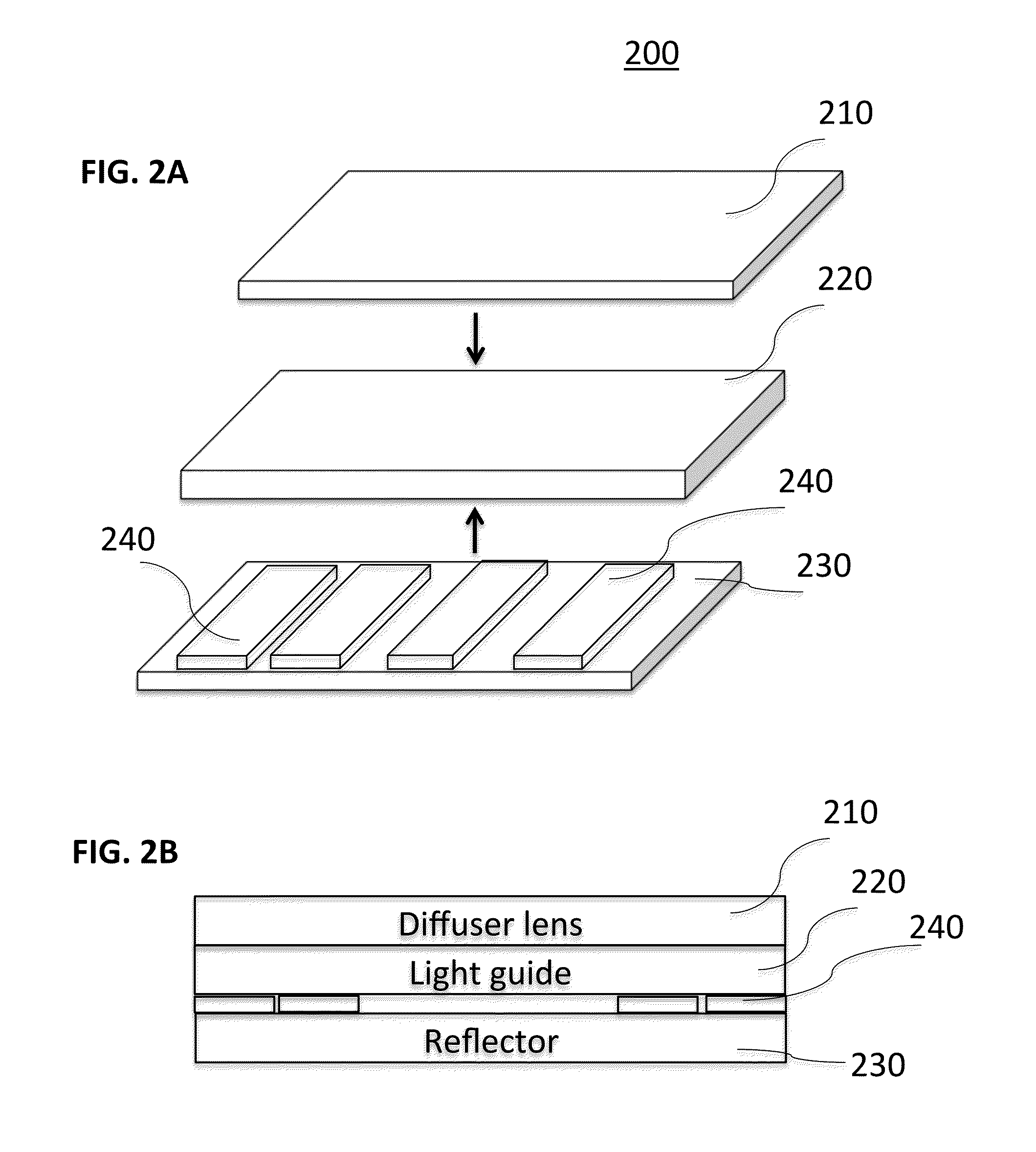
[0008]The invention features an edge-lit thin light-emitting system. The light-emitting system comprises a light guide sheet disposed between a reflector sheet and a diffuser lens sheet; at least one strip of LED arrays embedded in the optically clear material, the at least one strip is disposed on the edges of the light guide sheet with the light-emission side of LEDs facing the light gui...


PUM

PropertyMeasurementUnit
light transmittanceaaaaaaaaaa
reflectanceaaaaaaaaaa
perimeteraaaaaaaaaa

Abstract

A light-emitting system that utilizes light guides for edge lighting and back lighting applications is disclosed. A process of making the light-emitting system is also disclosed. An edge-lit thin light-emitting system can include a light guide sheet disposed between a reflector sheet and a diffuser lens sheet, at least one strip of LED arrays embedded in the optically clear material, the at least one strip is disposed on the edges of the light guide sheet with the light-emission side of LEDs facing the light guide; and, optionally, a frame disposed around the perimeter of the sheets; wherein the at least one strip of LED arrays is attached to the light guide sheet such that an air gap between the LEDs and the light guide is eliminated.

Description

RELATED APPLICATION DATA[0001]This application claims the priority of prior U.S. provisional application Ser. No. 61 / 636,694 filed on Apr. 22, 2012, which is hereby incorporated by reference herein in its entirety.TECHNICAL FIELD[0002]The invention relates to light-emitting systems and methods, and more specifically to light-emitting systems that utilize light guides for edge lighting and back lighting applications.BACKGROUND ART[0003]A light emitting diode (LED) often can provide light in a more efficient manner than an incandescent light source and / or a fluorescent light source. The relatively high power efficiency associated with LEDs has created an interest in using LEDs to displace conventional light sources in a variety of lighting applications. For example, in some instances LEDs are being used as traffic lights and to illuminate cell phone keypads and displays. The light emitting devices can be used in combination with light guides for illumination purposes such as backlight...

Claims


Application Information

Patent Timeline
Patent Type & Authority Applications(United States)
IPC IPC(8): G02B6/24F21V8/00
CPCG02B6/24G02B6/0065G02B6/0023G02B6/0055G02B6/0073Y10T29/49117
Inventor HODRINSKY, TODD W.SARAZIN, ROBERT M.
Owner LITEIDEAS
Why Eureka
Try Eureka