Attenuation correction in positron emission tomography using magnetic resonance imaging

a technology magnetic resonance imaging, which is applied in the field of attenuation correction of positron emission tomography using magnetic resonance imaging, can solve the problems of reducing quantitative accuracy and image quality degradation

Active Publication Date: 2013-10-24
GENERAL ELECTRIC CO
View PDF3 Cites 17 Cited by
  • Summary
  • Abstract
  • Description
  • Claims
  • Application Information

AI Technical Summary

Benefits of technology

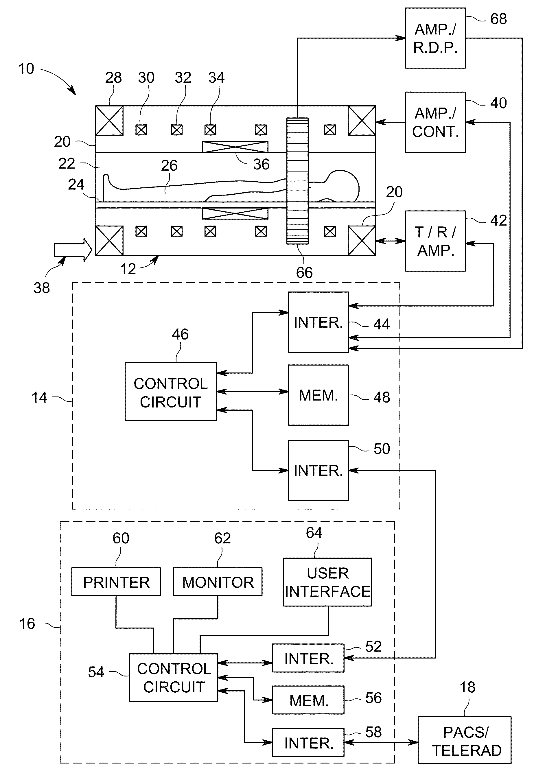
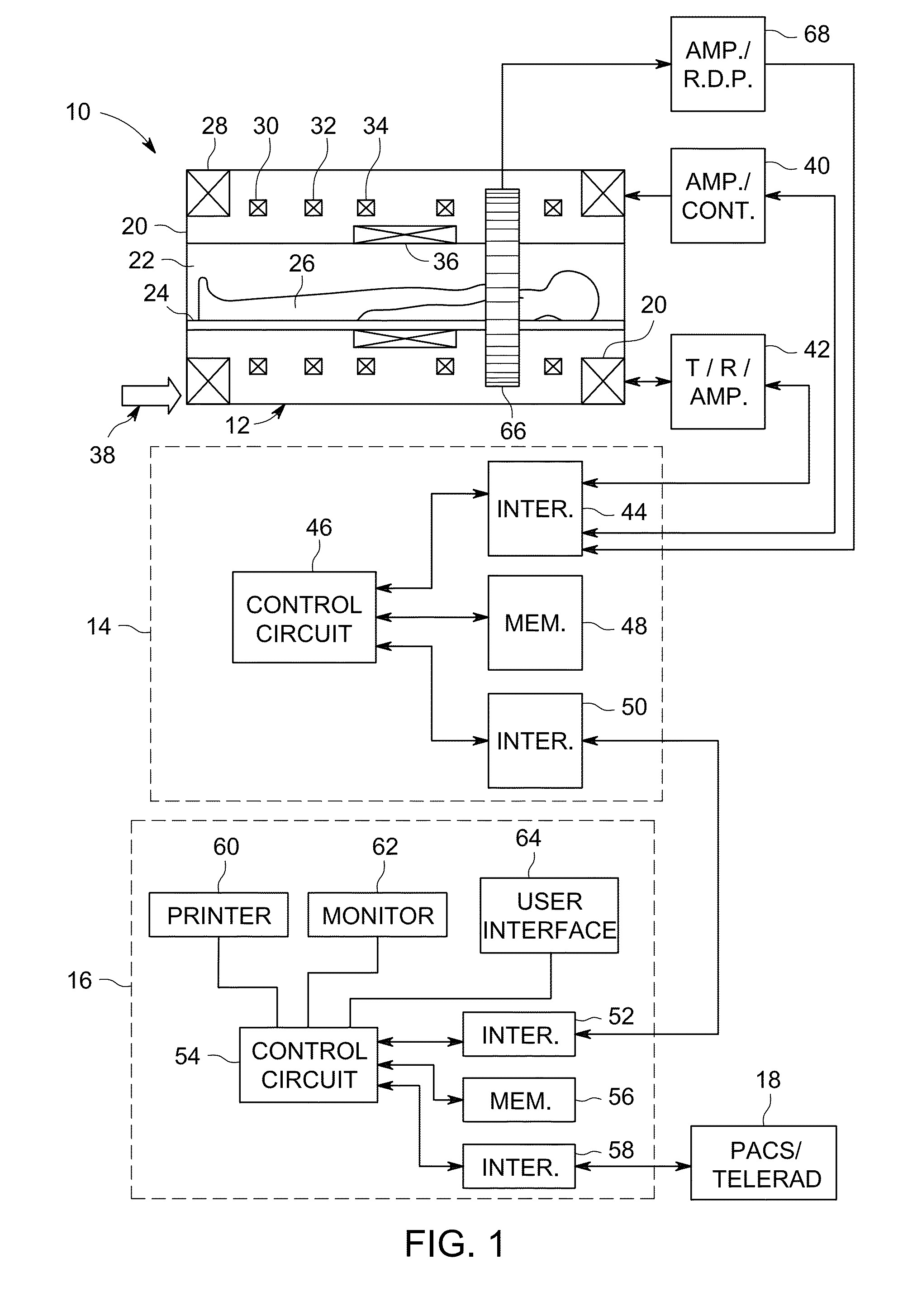
[0005]In another embodiment, one or more tangible, non-transitory, machine-readable media storing instructions executable by a processor are provided. The instructions are configured to cause the processor to perform the acts of causing an MR imaging system to perform a magnetic resonance (MR) imaging sequence to acquire MR image slices or volumes of a first station representative of a portion of a patient; applying a first phase field algorithm to the first station to determine a body contour of the patient in the first station; identifying a contour of a first anatomy of interest within the body contour of the first station using the first phase field algorithm or a second phase field algorithm; segmenting the first anatomy of interest based on the identified contour of the first anatomy of interest; correlating first attenuation information to the segmented first anatomy of interest; and modifying a positron emission tomography (PET) image based at least on the first correlated attenuation information.
[0006]In a further embodiment, a hybrid positron emission tomography/magnetic resonance (PET/MR) imaging system is provided. The system includes an opening configured to receive a patient; a primary field magnet; a plurality of gradient field coils disposed about the opening; a radiofrequency (RF) transmit coil; a plurality of RF receiving coils; a photodetector d

Problems solved by technology

Attenuation, or the phenomenon of reduction in the number of photons detected as compared to the

Method used


Image

  • Attenuation correction in positron emission tomography using magnetic resonance imaging
  • Attenuation correction in positron emission tomography using magnetic resonance imaging
  • Attenuation correction in positron emission tomography using magnetic resonance imaging

Examples


Embodiment Construction

[0022]One or more specific embodiments will be described below. In an effort to provide a concise description of these embodiments, all features of an actual implementation may not be described in the specification. It should be appreciated that in the development of any such actual implementation, as in any engineering or design project, numerous implementation-specific decisions must be made to achieve the developers' specific goals, such as compliance with system-related and business-related constraints, which may vary from one implementation to another. Moreover, it should be appreciated that such a development effort might be complex and time consuming, but would nevertheless be a routine undertaking of design, fabrication, and manufacture for those of ordinary skill having the benefit of this disclosure.

[0023]When introducing elements of various embodiments of the present invention, the articles “a,”“an,”“the,” and “said” are intended to mean that there are one or more of the ...


PUM


Abstract

In one embodiment, a method includes performing a magnetic resonance (MR) imaging sequence to acquire MR image slices or volumes of a first station representative of a portion of a patient; applying a first phase field algorithm to the first station to determine a body contour of the patient in the first station; identifying a contour of a first anatomy of interest within the body contour of the first station using the first phase field algorithm or a second phase field algorithm; segmenting the first anatomy of interest based on the identified contour of the first anatomy of interest; correlating first attenuation information to the segmented first anatomy of interest; and modifying a positron emission tomography (PET) image based at least on the first correlated attenuation information.

Description

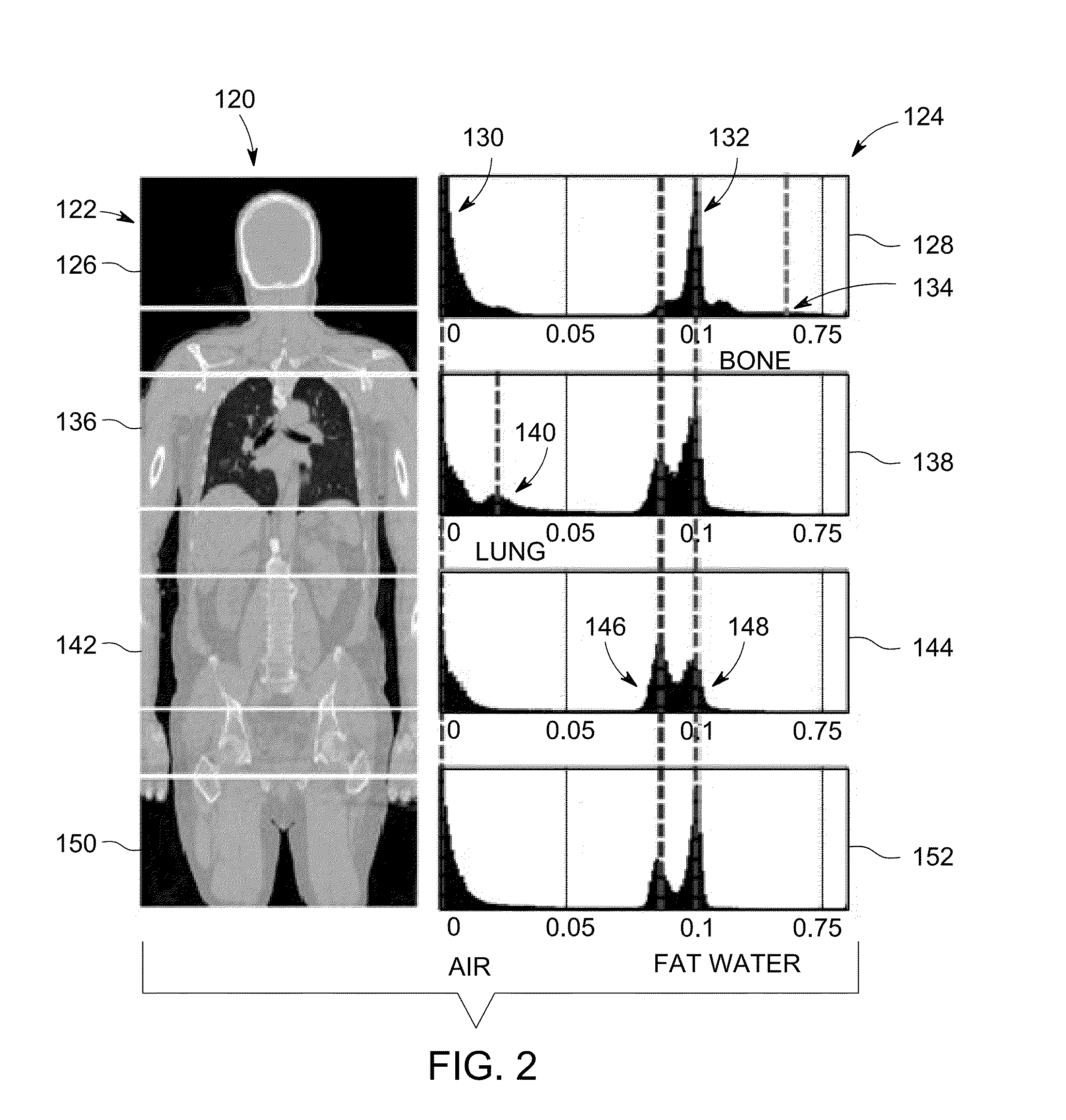
BACKGROUND[0001]In a positron emission tomography (PET) imaging system, a radionuclide is injected into a subject of interest. As the radionuclide decays, positrons are emitted that collide with electrons, resulting in an annihilation event that emits pairs of gamma particles. The pairs of gamma particles impact a detector array, which allows localization of the origin of the annihilation event. After a series of events are detected, localized concentrations of the radionuclide can be ascertained, leading to a functional diagnostic image.[0002]As PET data is acquired, attenuation of some of the emitted photons may occur. Attenuation, or the phenomenon of reduction in the number of photons detected as compared to the amount of photons emitted, can lead to degraded image quality and reduced quantitative accuracy. Accordingly, in certain situations, such as patient imaging, PET imaging is combined with X-ray computed tomography (CT) imaging to correct for such attenuation. Because CT i...

Claims


Application Information

Patent Timeline
IPC IPC(8): A61B5/055A61B6/03A61B6/02
CPCA61B5/0035A61B5/055A61B6/037A61B6/463A61B6/5247A61B6/582G01R33/481G01R33/485G01R33/5602G01R33/56383
Inventor THIRUVENKADAM, SHESHADRISHANBHAG, DATTESH DAYANANDMULLICK, RAKESHWIESINGER, FLORIANKAUSHIK, SANDEEP SURYANARAYANA
Owner GENERAL ELECTRIC CO
Why Eureka
Try Eureka