
Work machine and components thereof

a technology of work machines and components, applied in the field of work machines, can solve the problems of limiting the flexibility of operation, unable to perform the operation during the night, and no operation can be exactly in the same manner

Active Publication Date: 2013-10-24
MAMIYA
View PDF3 Cites 41 Cited by
  • Summary
  • Abstract
  • Description
  • Claims
  • Application Information

AI Technical Summary

Benefits of technology

The present invention relates to a work machine capable of traveling along a contour service path and adjacent straight service paths without leaving any tasks unattended. The machine is controlled to turn at intersections between the contour service path and the straight service paths, allowing for flexible steering operations while minimizing passes over a target area. The technical effect of this invention is the provision of a work machine that can efficiently and safely complete tasks while minimizing damage to the environment.

Problems solved by technology

In addition, when it is necessary to make several passes on the same point, no operation can be done exactly in a same way if the operation relies on the memory and feeling of the operator.
These operations cannot be done during the night time because the lawn motor is not visible from the operator.
In addition, a process of steering and a target area are limited due to the necessary steps of preventing accumulation of the angle detection errors, which restricts the flexibility of the operation.
In addition, the lawn is mown always in a semi-circular shape at the start and end points of lawn mowing, with a possibility of leaving patches of grass unmowed.
This means that it is impossible to mow the lawn along a path that is smaller than the minimum turning radius of the lawn mower regardless of the width of the cutting blade(s).
The aforementioned problems associated with the lawn mowers disclosed in Japanese Patent Laid-Open Nos. 9-37610 and 2001-344017 also occur in driving cultivating machines such as tractor for agricultural or farm works as well as driving of sweeper or cleaner robots.

Method used


Image

  • Work machine and components thereof
  • Work machine and components thereof
  • Work machine and components thereof

Examples


first embodiment

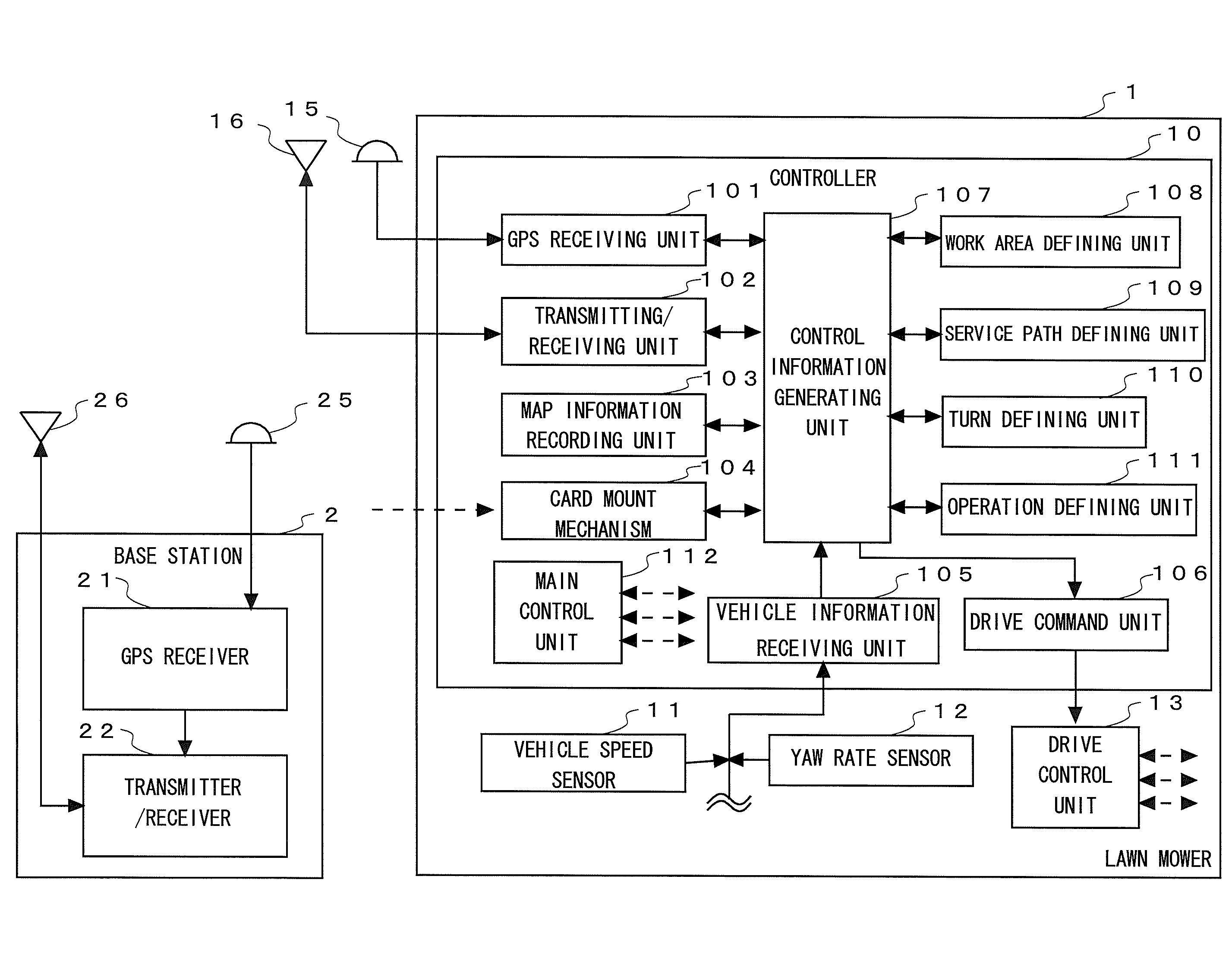
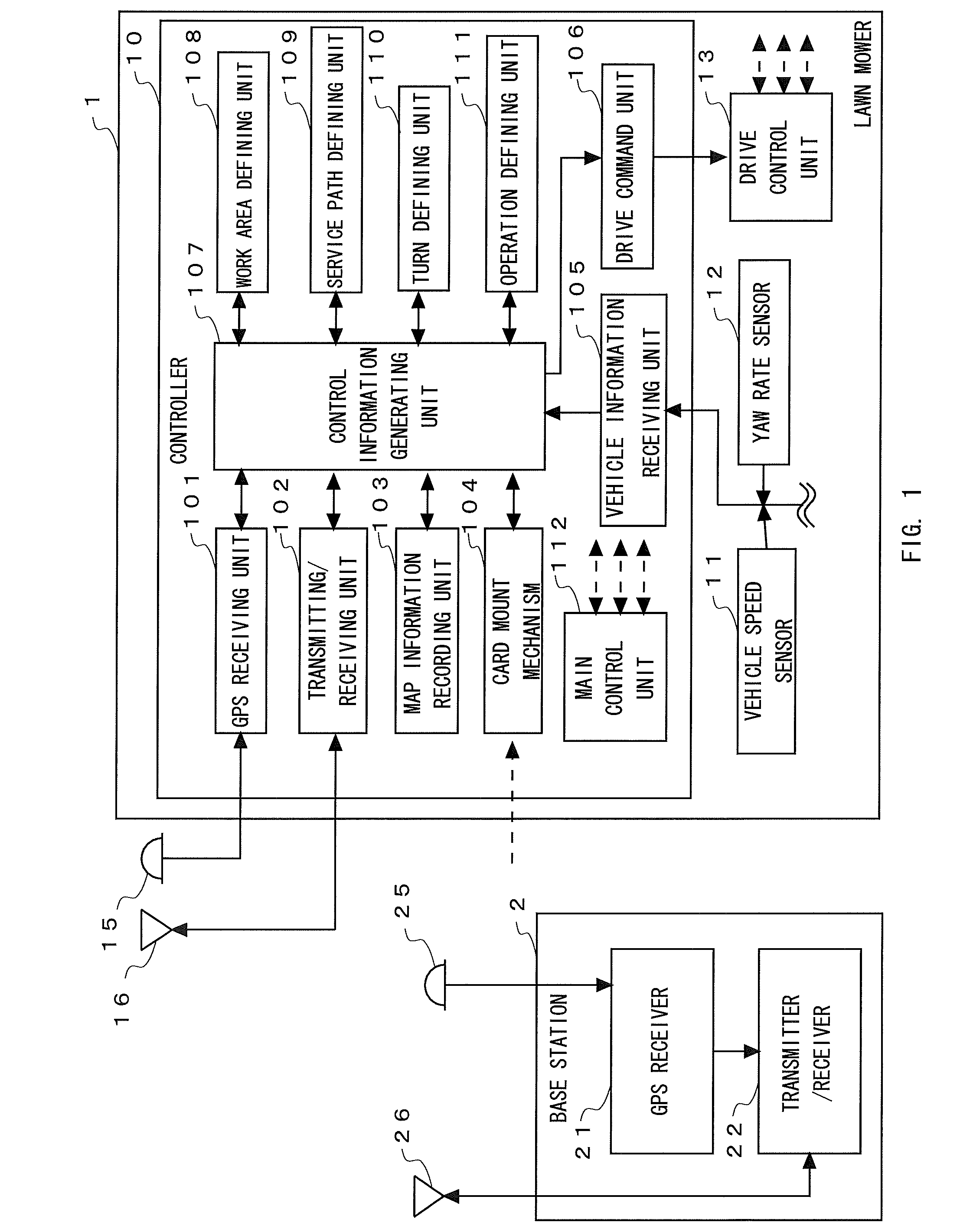
[0045]FIG. 1 shows a block diagram of an entire configuration of devices required for lawn mowing. This embodiment illustrates a motor-driven lawn mower 1 that can mow the grass in a golf field while measuring a current position of the mower itself by using communication information and GPS data from a base station 2 using differential GPS.

[0046]The base station 2 serves as a reference station for the differential GPS and comprises a GPS receiver 21, a transmitter / receiver 22, a GPS antenna 25, and a communication antenna 26. The base station 2 is located at a point with known longitude, latitude, and altitude. The GPS receiver 21 generates correction information for use in correcting an error in position information indicating the position of the motor-driven lawn mower 1. This correction information is appropriately sent to the motor-driven lawn mower 1 through the transmitter / receiver 22 and the communication antenna 26. The timing of sending the correction information to the mot...


PUM


Abstract

To provide a work machine that can make minimum passes over a target area without leaving any tasks with flexible steering operations. A controller 10 mounted on a motor-driven lawn mower 1 determines intersections between a contour service path and a pair of straight service paths that are adjacent to each other in which the motor-driven lawn mower 1 travels along the straight service paths in opposite directions, and sets (records) a turning behavior including backward movement of the motor-driven lawn mower connecting the adjacent intersections in a configuration file. The information recorded in the configuration file is read during the operation to move the motor-driven lawn mower along the contour service path 50 and the straight service paths on anywhere other than the aforementioned intersections and to turn in accordance with the turning behavior when the motor-driven lawn mower reaches one of the intersections.

Description

BACKGROUND OF THE INVENTION [0001]1. Technical Field[0002]The present invention relates to a work machine such as a motor-driven lawn mower or a sweeper used in fields or grounds such as golf fields and soccer grounds, banks of a river, parks and green, and gardens, and components thereof.[0003]2. Background Art[0004]Golf fields with two or more courses mow the lawn several times a year. Mowing putting green or fairway of a golf field is done by driving a lawn mower with an operator or by the remote control of it on which wired or wireless remote control device is mounted.[0005]Golf fields have a large lawned area. In particular, putting green requires having proper lawn surface with equal height of the cut with high accuracy while avoiding any patches of grass left unmowed. With this regard, the operator typically observes the actual movement of the lawn mower with his or her eyes and controls a controller to determine an area or path to be mowed, when the lawn mower is controlled ...

Claims


Application Information

Patent Timeline
Patent Type & Authority Applications(United States)
IPC IPC(8): A01D34/00G05D1/02
CPCA01D34/008G05D1/021G05D1/0219G05D1/0274G05D1/0278
Inventor YAZAKI, NOBORUSUKAGAWA, SUSUMUIGETA, KENICHIRO
Owner MAMIYA
Learn More