

brushcutter
a brush cutter and brush technology, applied in the field of brush cutters, can solve the problems of easy damage to the brush housing of the clutch, and achieve the effect of reducing the risk of damage to the brush housing
- Summary
- Abstract
- Description
- Claims
- Application Information
AI Technical Summary
Benefits of technology
Problems solved by technology
Method used
Image

Examples
Embodiment Construction
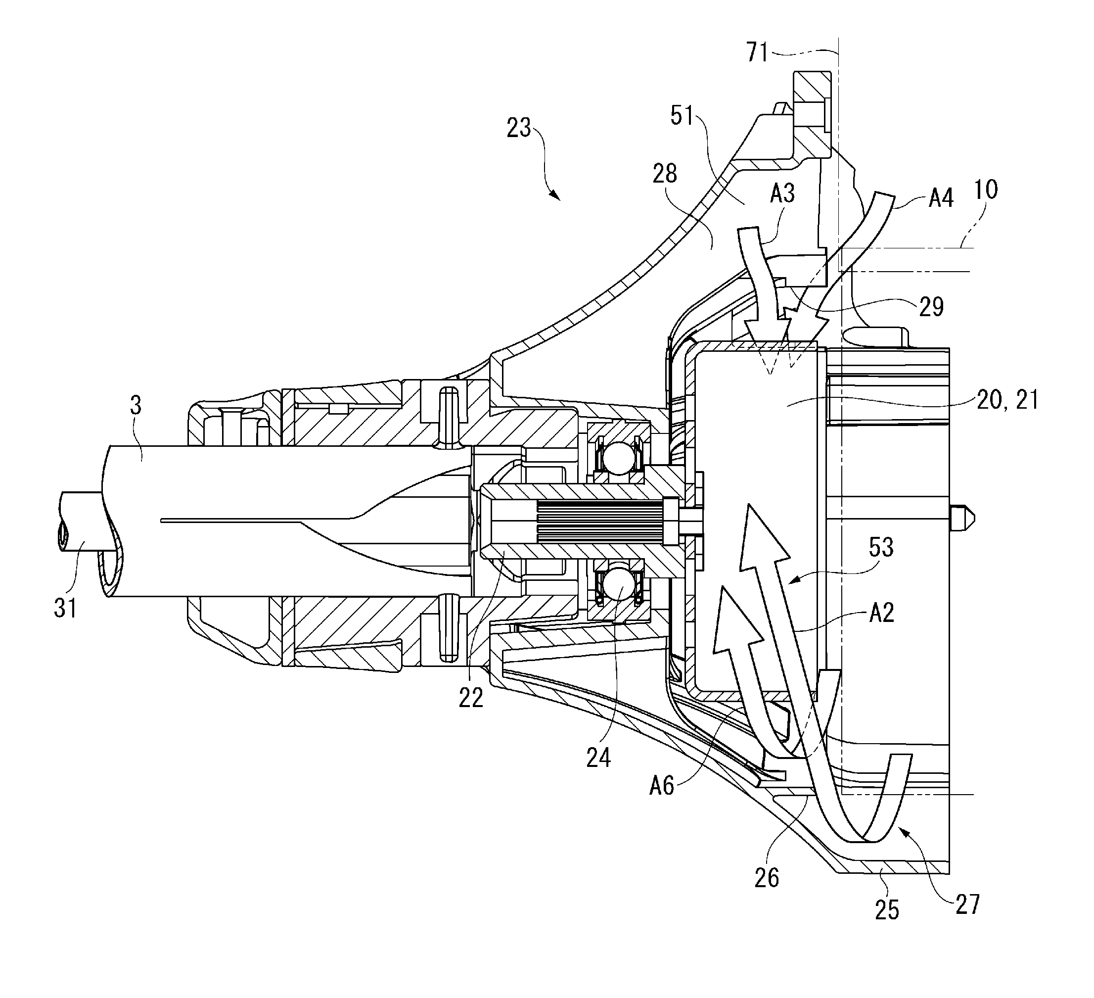
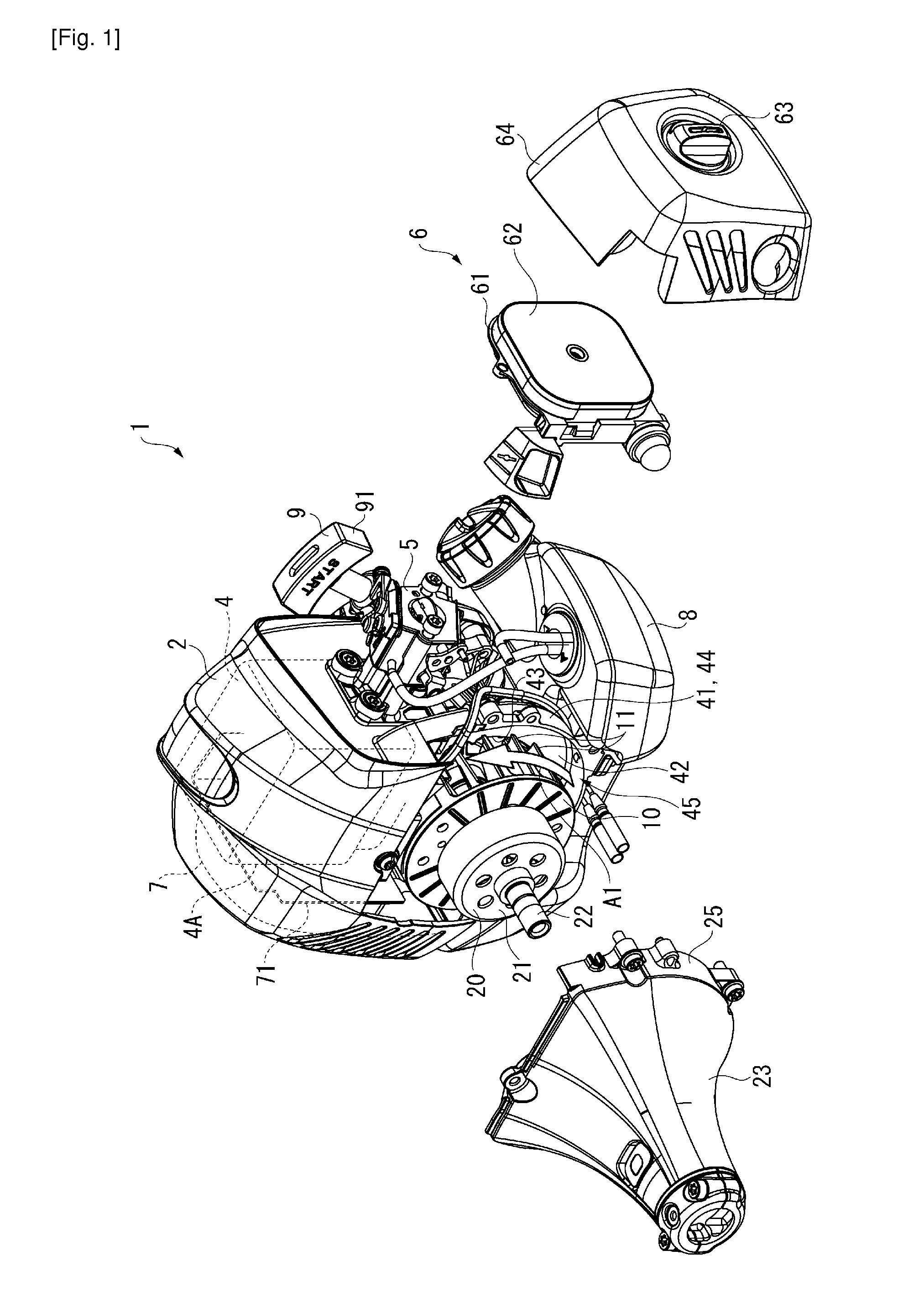
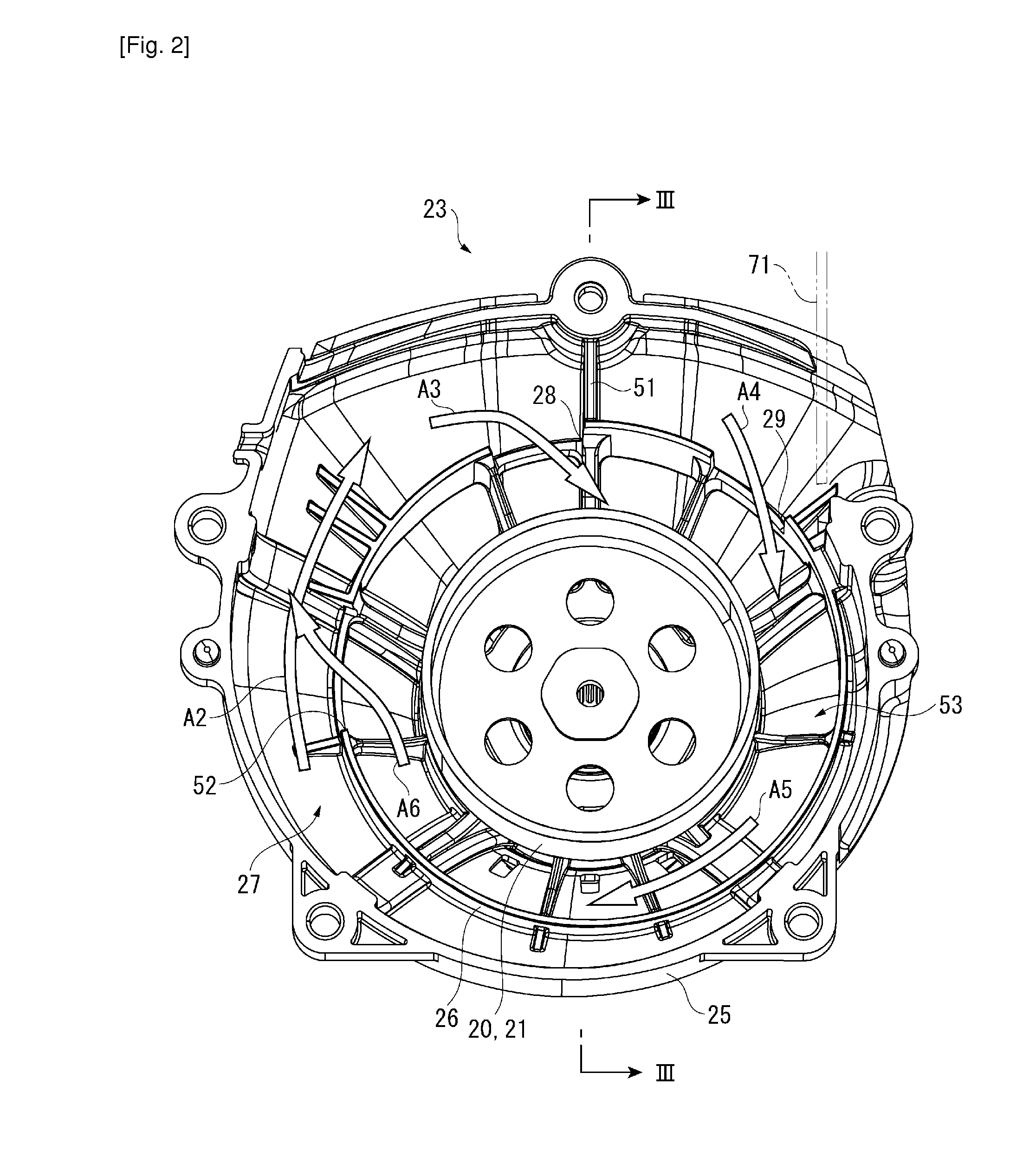
[0029]As shown in FIGS. 1 to 3, a brushcutter 1 includes: a main body 2 that includes a single-cylinder two-stroke engine 4 as a main component; an operating rod 3 having a base end connected to the body 2; an attachment (e.g. chip saw and nylon cutter) attached to another end of the operating rod 3; and a handle attached to a part of the operative rod 3. The engine 4 may be a four-stroke engine.
[0030]In the body 2, a carburetor 5 is attached to the engine 4 and an air cleaner 6 is attached to the carburetor 5. An exhaust muffler 7 is attached to the engine 4 at a side opposite to the carburetor 5. A fuel tank 8 is attached to a lower side of the engine 4. Fuel inside the fuel tank 8 is sucked by the carburetor 5.
[0031]The air cleaner 6 includes: a cleaner case 61 screwed to the carburetor 5; a spongelike element 62 housed in the cleaner case 61; and a cleaner cover 64 attached to the cleaner case 61 by an operating screw 63.
[0032]A recoil starter 9 having an operating knob 91 with ...
PUM
 Abstract
Description
Claims
Application Information