Soft Start Scheme Under Low Voltage Power

a low voltage power and soft start technology, applied in power conversion systems, amplifiers with semiconductor devices/discharge tubes, instruments, etc., can solve the problem that the conventional soft start driver circuit cannot be qualified i

Active Publication Date: 2013-10-31
ANPEC ELECTRONICS CORPORATION
View PDF2 Cites 8 Cited by
  • Summary
  • Abstract
  • Description
  • Claims
  • Application Information

AI Technical Summary

Benefits of technology

[0008]It is therefore an objective of the invention to provide a soft start circuit and driving method thereof which avoids the in-rush current generation of the following application circuit, so as to provide a protection mechanism to the following application circuit.

Problems solved by technology

However, when the error amplifier 10 just initiates to have a larger difference between the feedback voltage VFB and the reference voltage VREF, generation of the control signal EO accompanies an in-rush current, which can possibly cause damage of the following application circuit for receiving the control signal EO.
Also, the conventional soft start driver circuit can not be qualified if the N-type MOS transistor is utilized as the input stage circuit.

Method used


Image

  • Soft Start Scheme Under Low Voltage Power
  • Soft Start Scheme Under Low Voltage Power
  • Soft Start Scheme Under Low Voltage Power

Examples


Embodiment Construction

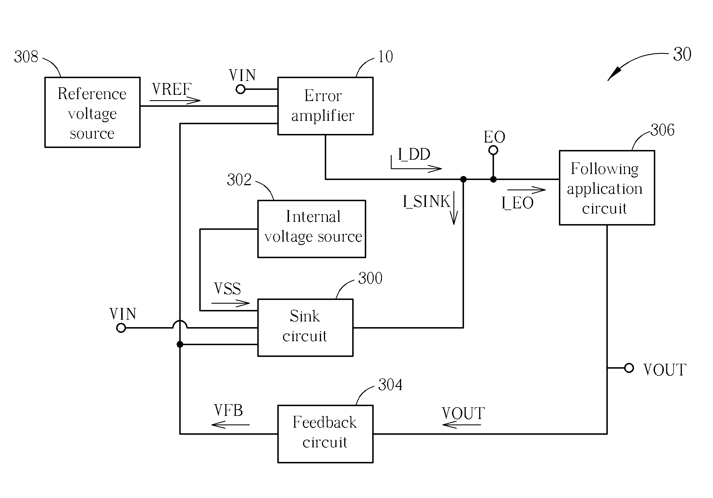
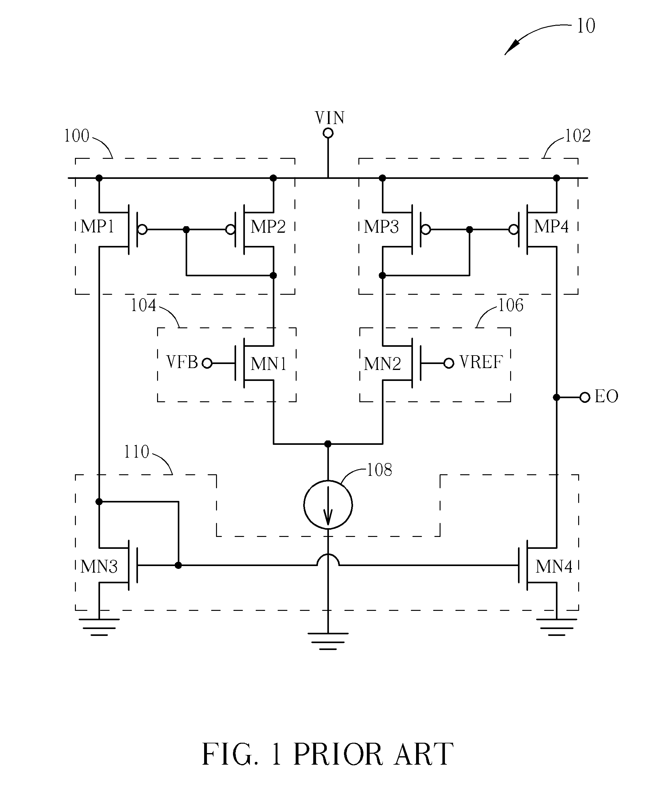
[0019]Please refer to FIG. 3, which illustrates a schematic diagram of a soft start circuit 30 according to an embodiment of the invention. As shown in FIG. 3, the soft start circuit 30 not only includes the error amplifier 10 of the prior ant, but also includes a sink circuit 300, an internal voltage source 302, a feedback circuit 304, a following application circuit 306 and a reference voltage source 308. The error amplifier 10 is coupled to the reference voltage source 308, the sink circuit 300 and the following application circuit 306 to receive an input voltage VIN, a reference voltage VREF generated by the reference voltage source 308 and a feedback voltage VFB. The detailed schematic diagram and operation of the error amplifier 10 is described in the above paragraphs, and is not described hereinafter. Besides, the sink circuit 300 is coupled to the internal voltage source 302 and the feedback circuit 304 to receive a soft start voltage VSS generated by the internal voltage so...


PUM


Abstract

A soft start circuit includes an error amplifier for generating a control signal according to an input voltage, a feedback voltage and a reference voltage, a feedback circuit for generating the feedback voltage according to an output voltage, an internal voltage source for generating a soft start voltage, and a sink circuit including a first transformation module for generating a first transformation current according to the soft start voltage, a second transformation module for generating a second transformation current according to the feedback voltage, a comparison module coupled to the first transformation module and the second transformation module for generating a comparison result according to the first transformation current and the second transformation current, and an output module coupled to the comparison module for generating a sink current according to the comparison result, so as to control the control signal.

Description

BACKGROUND OF THE INVENTION[0001]1. Field of the Invention[0002]The present invention relates to a soft start circuit and a driving method thereof, and more particularly, to a soft start circuit and a driving method thereof which utilize a soft start voltage to correspondingly generate a sink current for soft start operation.[0003]2. Description of the Prior Art[0004]Electronic devices usually have different elements which operate with different operational voltages. Thus, it is necessary to utilize different DC-DC voltage converters in order to achieve different voltage modulations, such as modulation for raising voltage values or dropping voltage values, and to maintain them at predetermined voltage values. Many types of DC-DC voltage converters have been widely developed and are derived from the buck / step down converter or the boost / step up converter. The buck converter can decrease an input DC voltage to a default voltage level, and the boost converter can increase the input DC ...

Claims


Application Information

Patent Timeline
Patent Type & Authority Applications(United States)
IPC IPC(8): G05F1/10
CPCH02M1/36H03F3/45192H03F2203/45674
Inventor CHEN, CHIH-NINGCHEN, YEN-MING
Owner ANPEC ELECTRONICS CORPORATION
Why Eureka
Try Eureka