Balun

Active Publication Date: 2013-10-31
GE MEDICAL SYST GLOBAL TECH CO LLC
View PDF7 Cites 4 Cited by
  • Summary
  • Abstract
  • Description
  • Claims
  • Application Information

AI Technical Summary

Problems solved by technology

Above a S wave band, a balun can be implemented by using a ¼ wavelength transmission line easily, but for a UHF, VHF and even lower wave bands, because of longer wavelength, and limited by size, it can hardly be realized in this manner.
The balun containing ferrite material cannot be used in a magnetic field environment, becaus

Method used


Image

  • Balun
  • Balun
  • Balun

Examples


Embodiment Construction

[0014]Following is a further explanation of embodiments of the present invention in combination with figures.

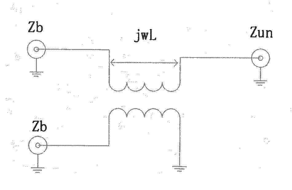
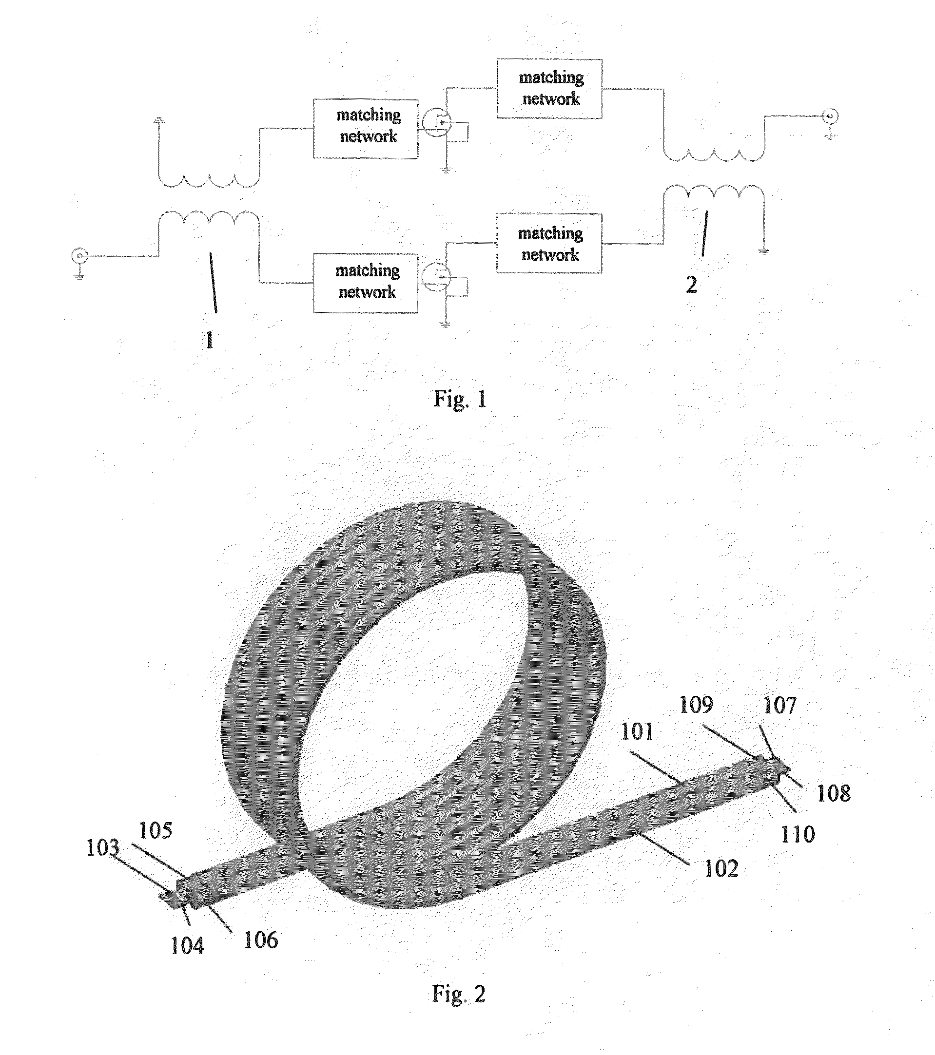
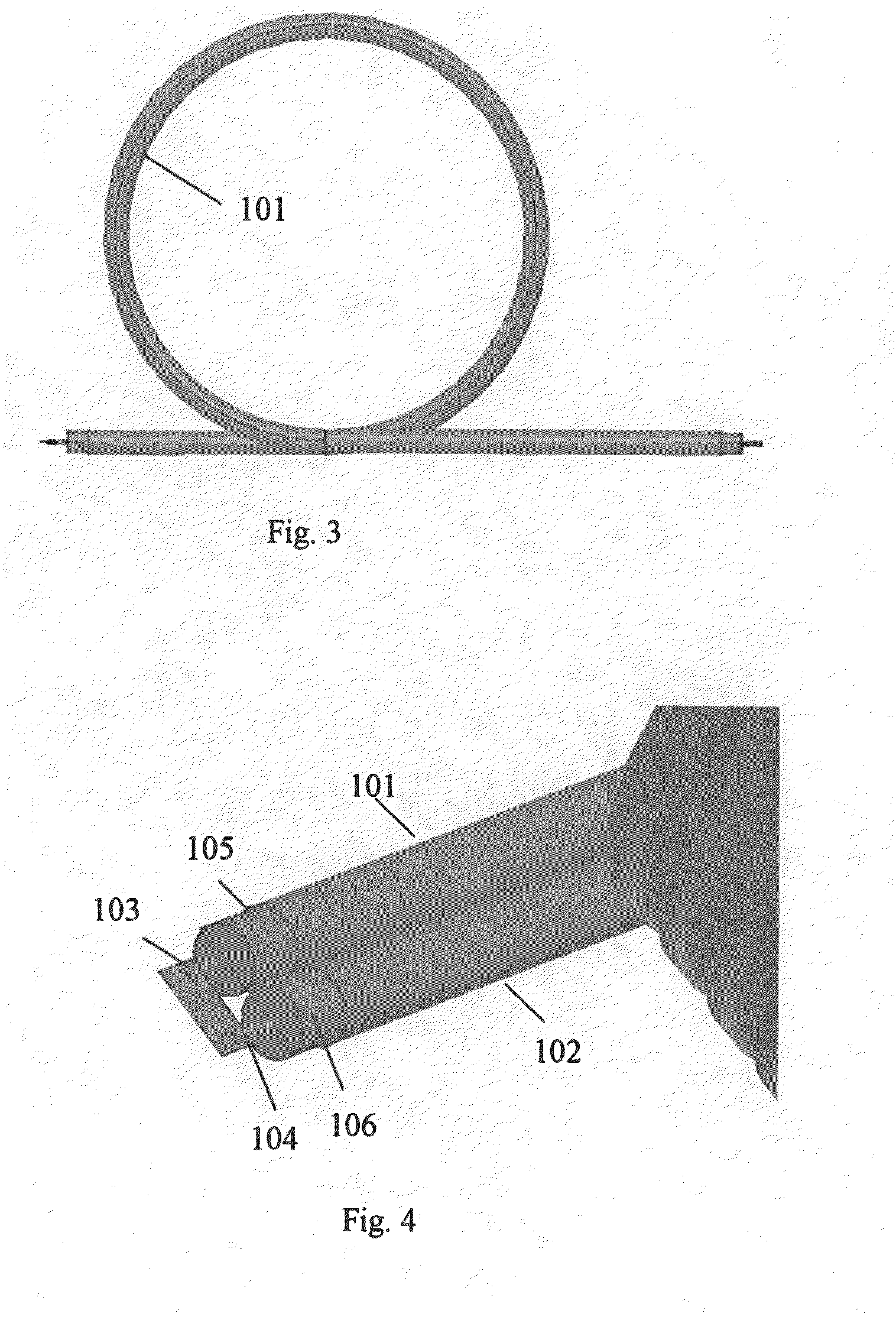
[0015]In accordance with an embodiment of the present invention, a balun comprising at least two coaxial cables 101 and 102 is provided. In at least one embodiment, the coaxial cables are 50 ohm coaxial cables each having a length of approximately 40 cm; however, as would be recognized by those having ordinary skill in the art, the ohm rating and / or the length of the cables may be varied as required.

[0016]As shown in FIG. 1, at least two coaxial cables 101 and 102 are arranged closely together and wound into at least one loop. In some embodiments, the at least two coaxial cables 101 and 102 are wound in the shape / form of a helix comprising at least three loops. In some embodiments, the winding shape of each loop of coaxial cables may take the form of a circle as shown in FIG. 3; however, the shape of each loop can take the form of any of numerous shapes known to those skilled...


PUM


Abstract

Embodiments of the present invention relate to the technical field of RF circuits, and in particular, to a balun. In an embodiment of the present invention, a balun is provided which comprises at least two coaxial cables, each of which is wound into at least one loop, and the inner and outer conductors of one end of all coaxial cables are connected respectively to each other and the inner and outer conductors of the other end are also connected to each other. The novel balun according to the embodiments of the present invention has a small size but a large power capacity and low cost, and can be used in a magnetic field environment.

Description

BACKGROUND TO THE INVENTION[0001]This invention relates to the technical field of circuits, and in particular, to a balun.[0002]In general, a RF power amplifier usually uses a push-pull circuit. FIG. 1 shows a typical push-pull circuit. In the circuit, a balun (also known as balanced feeding converter or transmission line balancing device) is an indispensable component, wherein the input balun 1 is used to convert the signal on the unbalanced transmission line into a balanced input for the power amplifier, while the output balun 2 is used to convert the balanced output of the power amplifier onto an unbalanced load.[0003]Above a S wave band, a balun can be implemented by using a ¼ wavelength transmission line easily, but for a UHF, VHF and even lower wave bands, because of longer wavelength, and limited by size, it can hardly be realized in this manner. The practice in the prior art is using ferrite material to realize the balun.[0004]Some RF power amplifiers need to be used in a ma...

Claims


Application Information

Patent Timeline
IPC IPC(8): H01P5/10
CPCH03H7/42H01P5/10
Inventor LIU, YUPENG, QIBINLIAO, ANMOUXING, HAOYANGZHAO, CHENXINGHUANG, HAI
Owner GE MEDICAL SYST GLOBAL TECH CO LLC
Why Eureka
Try Eureka