

Scanning-type image display device and its image display method
a display device and scanning-type technology, applied in the field of scanning-type image display devices, to achieve the effect of inhibiting the decrease of resolution power
- Summary
- Abstract
- Description
- Claims
- Application Information
AI Technical Summary
Benefits of technology
Problems solved by technology
Method used
Image

Examples
first exemplary embodiment
[0077]FIG. 4 is a block diagram illustrating the configuration of a scanning-type image display device according to a first exemplary embodiment of the present invention.
[0078]Referring to FIG. 4, the scanning-type image display device is of a rear projection type, and comprises light source 1, condenser lens 2, scanning means 3, lookup table 6, control means 10, and projection plane 9. The distance from scanning means 3 to projection plane 9 is fixed.
[0079]Control means 10 is adapted to control the operation of the entire scanning-type image display device, and comprises laser modulation means 4 and modulation waveform output calculation means 5.
[0080]Video signal 7 from an external device is supplied to modulation waveform output calculation means 5. Synchronization signal 8, which is used for vertical synchronization and horizontal synchronization in displaying images through image signal 7, is supplied to modulation waveform output calculation means 5 and scanning means 3 from t...
second exemplary embodiment
[0121]FIG. 9 is a block diagram illustrating the configuration of a scanning-type image display device according to a second exemplary embodiment of the present invention.
[0122]The scanning-type image display device according to the present exemplary embodiment differs from the first exemplary embodiment in that condenser lens 2 is replaced by variable focusing lens 41, and focus control means 42 for controlling variable focusing lens 41 has been added.
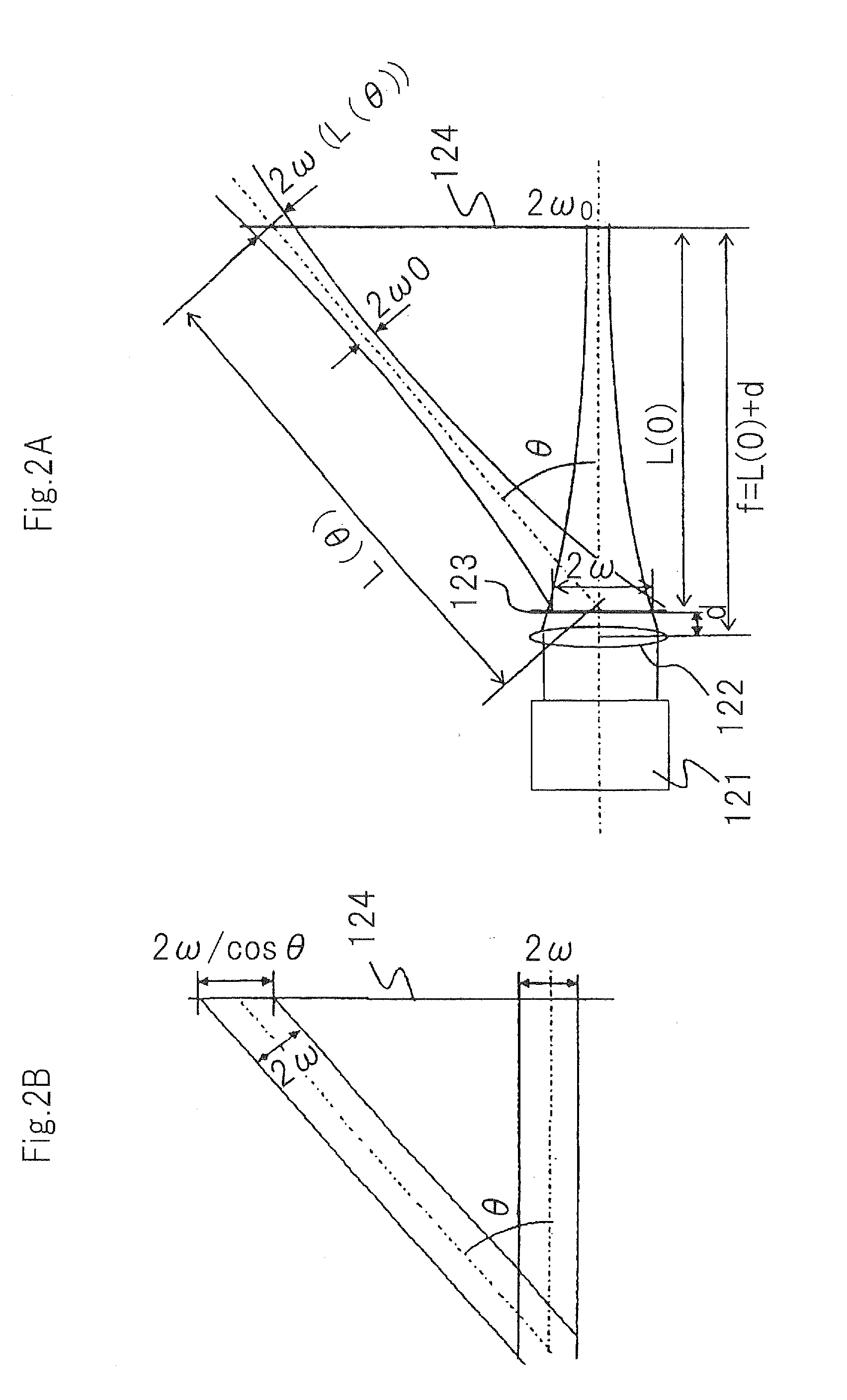
[0123]Modulation waveform output and calculation means 5 calculates a focal point distance depending on scanning angle θ of scanning means 3, based on characteristic data obtained from lookup table 6, and supplies the calculation result of the focal point distance to focus control means 42. The relationship between scanning angle θ of scanning means 3 and the focal point distance of variable focusing lens 41 may be calculated in accordance with the aforementioned Equation 3.
[0124]The calculation of the focal point distance in modulati...
specific examples
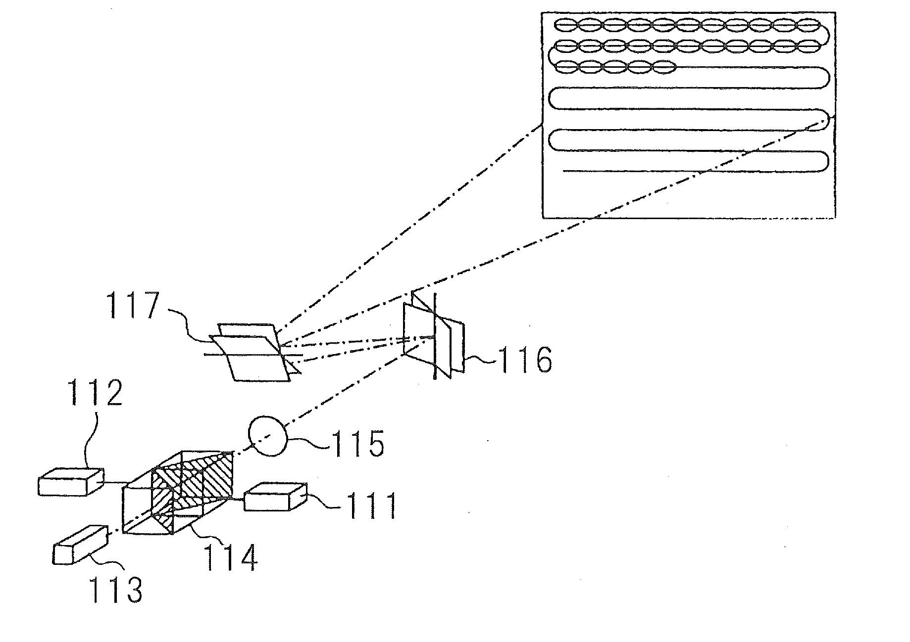
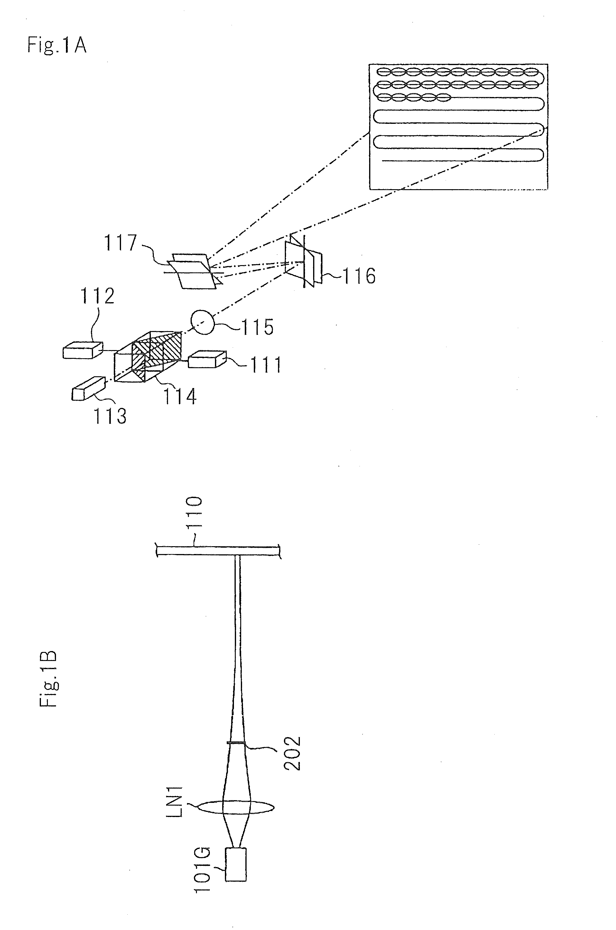
[0138]The aforementioned scanning-type image display devices according to the first and second exemplary embodiments each comprises a red laser light source, a green laser light source, and a blue light source, as light source 1. The beam diameter of the laser light source for each color is 1000 μm.
[0139]The red laser light source is a semiconductor laser having a wavelength of 640 nm. The blue laser light source is a semiconductor laser having a wavelength of 440 nm. The modulation of the red and blue light sources is carried out through a current control.
[0140]The green laser light source is a laser light source that utilizes the second harmonic (532 nm) of an infrared laser light having a wavelength of 1064 nm. The modulation of the green laser light source is carried out using an acoustooptical element.
[0141]The focal point distance of condenser lens 2 is 400 mm. Scanning means 3 comprises a resonant micro-mechanical scanning element for horizontal scanning, and an electromagnet...
PUM
 Abstract
Description
Claims
Application Information